The lifespan of a sputter target is not measured in simple hours or days, but in the total energy it can absorb before failure. This is typically specified by the manufacturer in kilowatt-hours (kW-h). A target's actual lifetime in your system can range from a few dozen to several thousand hours, depending entirely on the material being sputtered, the power you apply, and the efficiency of your sputtering system.
A sputter target's life is a function of material erosion, not time. The core challenge is balancing maximum material utilization against the critical risks of process contamination and equipment damage as the target thins.
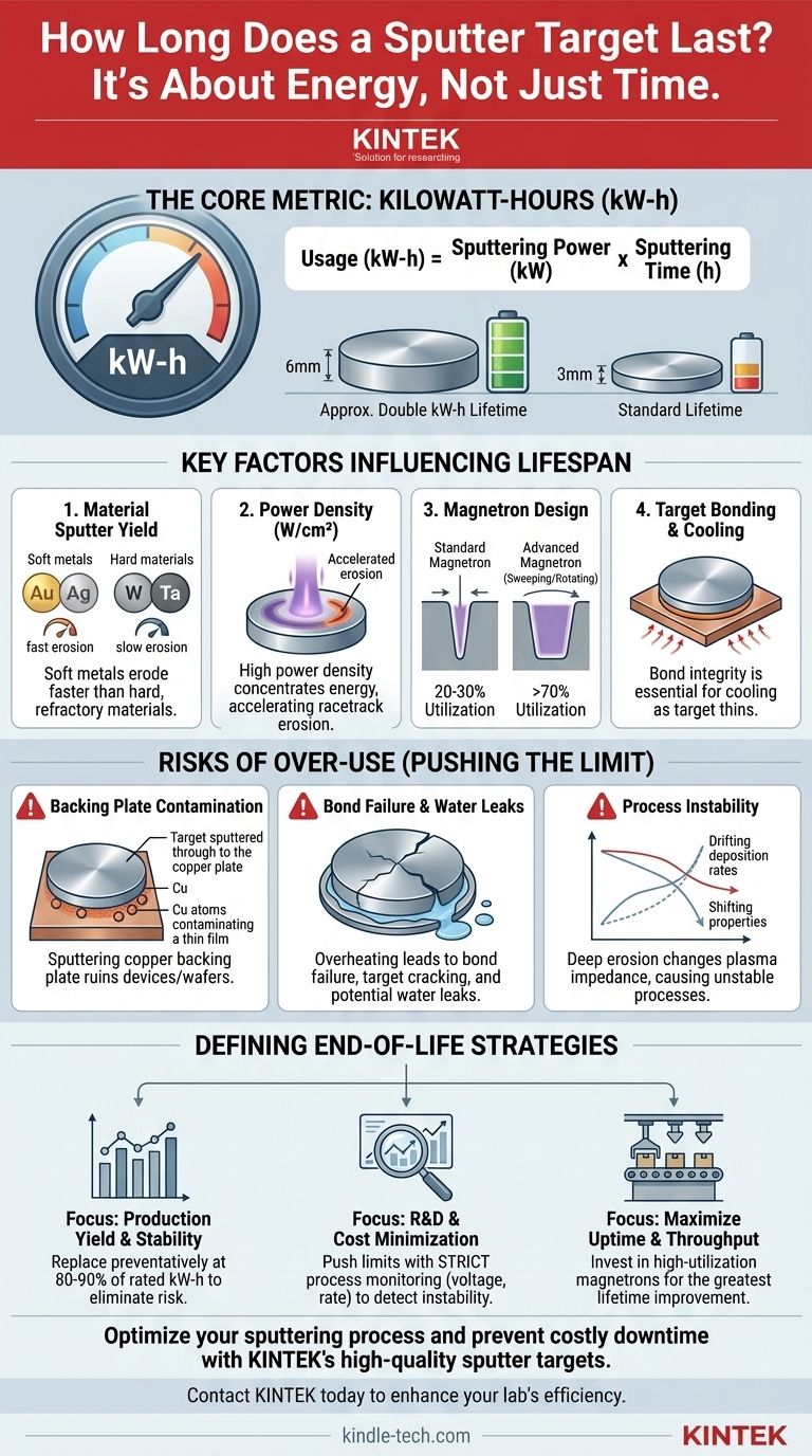
The Core Metric: Kilowatt-Hours (kW-h)
Why Not "Hours"?
Relying on "hours" is misleading because sputtering processes are not constant. A target run for 100 hours at a low power of 1 kilowatt (kW) experiences far less erosion than a target run for 100 hours at a high power of 10 kW.
Time is a variable, but energy delivered is the constant that dictates erosion.
Calculating Kilowatt-Hours
The kW-h rating represents the total energy the target can handle over its entire life. You can track your usage with a simple calculation:
Usage (kW-h) = Sputtering Power (kW) x Sputtering Time (h)
When your cumulative usage approaches the manufacturer's specified kW-h limit, it is time to plan for a replacement.
The Role of Target Thickness
The most direct factor in a target's kW-h rating is its thickness. A 6mm thick target has twice the usable material as a 3mm thick target and will, therefore, have approximately double the kW-h lifetime, assuming all other factors are equal.
Key Factors Influencing Target Lifespan
Beyond the manufacturer's rating, several operational factors determine how quickly a target is consumed.
Material Sputter Yield
Different materials erode at vastly different rates. Soft metals with high sputter yields, such as gold (Au) or silver (Ag), will erode much faster than hard, refractory materials with low yields, like tungsten (W) or tantalum (Ta).
Power Density
Power density, or the watts applied per unit area (W/cm²), has a major impact. High power densities concentrate the plasma energy, accelerating erosion within the magnetic trap area, often called the "racetrack."
Magnetron Design
The magnetron's magnetic field configuration is critical. It shapes the plasma and defines the erosion groove. An inefficient magnetron creates a deep, narrow groove, using only a small fraction of the target material (20-30% utilization) before it fails.
Advanced magnetrons with sweeping or rotating magnetic fields create a much wider erosion path, dramatically improving material utilization to over 70% and significantly extending the target's useful life.
Target Bonding and Cooling
Most targets are bonded to a copper backing plate for structural integrity and thermal cooling. The integrity of this bond is essential. As the target thins, its ability to dissipate heat decreases, putting stress on the bond and increasing the risk of failure.
Understanding the Trade-offs: Pushing a Target to Its Limit
Knowing when to stop is critical. Attempting to extract every last bit of material from a target introduces significant risks that almost always outweigh the cost of a new target.
The Risk of Backing Plate Contamination
This is the most common and costly failure mode. If you sputter completely through the target material, you will begin sputtering the copper backing plate. This introduces severe, and often invisible, copper contamination into your thin film, ruining your devices and potentially an entire batch of wafers.
Bond Failure and Water Leaks
As the target thins, localized heat increases dramatically. This can melt the indium bond holding the target to the backing plate, causing a loss of thermal contact. The target will then quickly overheat, crack, or warp, which can lead to a catastrophic water leak into your vacuum chamber if the vacuum seal is compromised.
Process Instability
As the erosion groove deepens, the distance between the magnets and the plasma changes. This alters the magnetic field strength at the target surface, which can change the plasma impedance. The result is a process that becomes unstable, with drifting deposition rates and shifting film properties, making run-to-run repeatability impossible.
Defining End-of-Life for Your Process
Proactively managing your target's life is key to a stable, high-yield process. Your strategy should align with your primary goal.
- If your primary focus is production yield and stability: Replace the target preventatively once it reaches 80-90% of its rated kW-h lifetime to eliminate any risk of contamination or downtime.
- If your primary focus is R&D and minimizing material cost: You can push the target closer to its limit, but you must implement strict process monitoring of deposition rate and cathode voltage to detect instability before a catastrophic failure occurs.
- If your primary focus is maximizing uptime and throughput: Invest in sputtering hardware with high-utilization magnetrons, as this provides the single greatest improvement in effective target lifetime.
Ultimately, treating your sputter target as a mission-critical, consumable component with a defined operational budget is the key to a reliable and efficient thin-film process.
Summary Table:
| Key Factor | Impact on Target Lifespan |
|---|---|
| Material Sputter Yield | High-yield materials (e.g., Au, Ag) erode faster than low-yield ones (e.g., W, Ta). |
| Power Density (W/cm²) | Higher power density concentrates energy, accelerating erosion in the racetrack. |
| Magnetron Design | Advanced magnetrons can increase material utilization from ~30% to over 70%. |
| Target Thickness | A thicker target (e.g., 6mm vs. 3mm) provides approximately double the kW-h lifetime. |
Optimize your sputtering process and prevent costly downtime.
Understanding the precise lifespan of your sputter targets is critical for maintaining high yield and process stability. KINTEK specializes in high-quality lab equipment and consumables, including sputter targets designed for maximum utilization and reliability. Our experts can help you select the right target material and configuration for your specific application, ensuring you get the most out of your investment while avoiding the risks of contamination and equipment failure.
Don't let target failure compromise your research or production. Contact our team today to discuss your needs and discover how KINTEK's solutions can enhance your laboratory's efficiency and throughput.
Visual Guide
Related Products
- Multifunctional Electrolytic Electrochemical Cell Water Bath Single Layer Double Layer
- Reference Electrode Calomel Silver Chloride Mercury Sulfate for Laboratory Use
- Laboratory CVD Boron Doped Diamond Materials
- Square Lab Press Mold for Laboratory Applications
- Electron Beam Evaporation Coating Oxygen-Free Copper Crucible and Evaporation Boat
People Also Ask
- What is the typical experimental system used with a double-layer water-bath electrolytic cell? Achieve Precise Electrochemical Control
- What are the procedures for after using a double-layer water-bath electrolytic cell? Ensure Equipment Longevity and Data Accuracy
- What steps should be taken before using a double-layer water-bath electrolytic cell? Ensure Accurate Electrochemical Results
- What is the typical volume range of the multifunctional electrolytic cell? Choosing the Right Size for Your Lab
- What are the key features of a double-layer water-bath electrolytic cell? Achieve Precise Temperature Control for Your Experiments