In magnetron sputtering, thickness uniformity is a critical measure of how consistently a thin film's thickness is maintained across the entire surface of the substrate. It is the difference between a perfectly even coating and one that is thicker in some areas and thinner in others, often expressed as a percentage deviation from the average thickness.
Achieving high thickness uniformity is not about a single setting, but about balancing the physical geometry of the sputtering system with the process parameters. The goal is to ensure that atoms ejected from the target material deposit evenly across the entire substrate area.
The Journey from Target to Substrate
The Basic Deposition Process
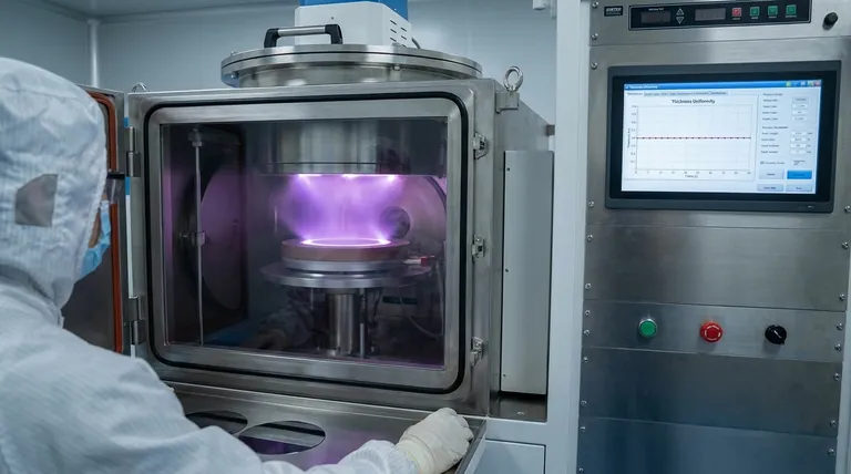
In any sputtering system, ions from a plasma bombard a source material, known as the target. This impact ejects atoms from the target, which then travel through the vacuum chamber and condense onto your component, the substrate.
The total thickness of this deposited film is controlled by maintaining a constant deposition rate over a specific period. The challenge lies in ensuring this rate is the same at every point on the substrate.
Why Uniformity is Critical
For most advanced applications, poor uniformity is a critical failure point. In precision optics, variations in thickness can distort light transmission. In semiconductors, it can lead to inconsistent electrical properties and device failure. In protective coatings, thin spots can become points of corrosion or wear.
Key Factors Controlling Film Uniformity
The final uniformity of a film is the result of several interacting factors. These can be broadly divided into system geometry and process parameters.
System Geometry: The Foundational Factor
The physical layout of your sputtering chamber has the most significant impact on uniformity.
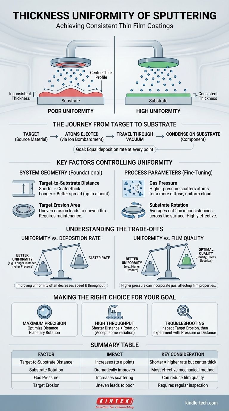
Target-to-Substrate Distance: This is the distance between the material source (target) and the substrate. A shorter distance increases the deposition rate but often results in a "center-thick" profile, as the center of the substrate receives more material. Increasing the distance allows the atom flux to spread out more, improving uniformity up to a point.
Target Erosion Area: In magnetron sputtering, a magnetic field confines the plasma to a specific region on the target, known as the "racetrack." The size, shape, and wear pattern of this erosion area directly determine the source of the sputtered atoms. An unevenly eroded target cannot produce a uniform coating.
Process Parameters: Fine-Tuning the Result
Once the geometry is set, process parameters are used to fine-tune the deposition.
Gas Pressure: The pressure of the inert gas (like Argon) in the chamber plays a crucial role. At very low pressures, atoms travel in a straight "line-of-sight" path, which can reduce uniformity. Increasing the pressure causes more collisions, scattering the sputtered atoms and creating a more diffuse, uniform coating cloud.
Substrate Rotation: This is the single most effective mechanical method for improving uniformity. By rotating the substrate during deposition, any inconsistencies in the material flux from the target are averaged out across the entire surface.
Understanding the Trade-offs
Achieving perfect uniformity often requires compromising on other process goals. This balance is central to sputtering process development.
Uniformity vs. Deposition Rate
There is a fundamental trade-off between uniformity and speed. Techniques used to improve uniformity, such as increasing the target-to-substrate distance or raising the gas pressure for more scattering, almost always decrease the deposition rate. This means the process takes longer, reducing throughput and increasing cost.
Uniformity vs. Film Quality
While higher gas pressure can improve uniformity, it also increases the chance of gas atoms becoming embedded in the growing film. This can alter the film's density, internal stress, and electrical or optical properties. The ideal pressure is one that provides acceptable uniformity without compromising the film's required performance characteristics.
Making the Right Choice for Your Goal
Your strategy for achieving uniformity should be dictated by the specific requirements of your application.
- If your primary focus is maximum uniformity for precision applications: Combine an optimized target-to-substrate distance with continuous, planetary substrate rotation.
- If your primary focus is high throughput and cost-efficiency: You may need to accept slightly lower uniformity by using a shorter target distance, but substrate rotation remains highly recommended to avoid major inconsistencies.
- If you are troubleshooting an existing process with poor uniformity: First, inspect the target's erosion track for abnormalities. Then, systematically experiment with small increases in gas pressure or target-to-substrate distance.
Ultimately, mastering thickness uniformity is about balancing the physics of the plasma with the geometry of your system to achieve a consistent and predictable outcome.
Summary Table:
| Factor | Impact on Uniformity | Key Consideration |
|---|---|---|
| Target-to-Substrate Distance | Increases with longer distance (up to a point) | Shorter distance = higher rate but center-thick profile |
| Substrate Rotation | Dramatically improves by averaging flux | Most effective mechanical method |
| Gas Pressure | Higher pressure increases scattering for better uniformity | Can reduce film quality by gas incorporation |
| Target Erosion | Uneven erosion leads to poor uniformity | Requires regular inspection and maintenance |
Achieve precise, uniform coatings for your lab's most demanding applications. KINTEK specializes in lab sputtering equipment and consumables, providing the reliable performance needed for semiconductors, optics, and advanced research. Let our experts help you optimize your process for superior results. Contact us today to discuss your specific coating requirements!
Visual Guide
Related Products
- Spark Plasma Sintering Furnace SPS Furnace
- Vacuum Induction Melting Spinning System Arc Melting Furnace
- Chemical Vapor Deposition CVD Equipment System Chamber Slide PECVD Tube Furnace with Liquid Gasifier PECVD Machine
- Customer Made Versatile CVD Tube Furnace Chemical Vapor Deposition Chamber System Equipment
- Vacuum Cold Mounting Machine for Sample Preparation
People Also Ask
- What are the advantages of CAMI/SPS for W-Cu composite preparation? Reduce cycles from hours to seconds.
- Why are Spark Plasma Sintering (SPS) furnaces or hot presses utilized in the preparation of Li3PS4 solid electrolytes?
- What are the fundamentals of spark plasma sintering process? Unlock Rapid, High-Performance Material Consolidation
- What technical advantages does a Spark Plasma Sintering (SPS) furnace offer for LZP ceramics? Enhance Ionic Conductivity
- What is the difference between spark plasma sintering and flash sintering? A Guide to Advanced Sintering Methods