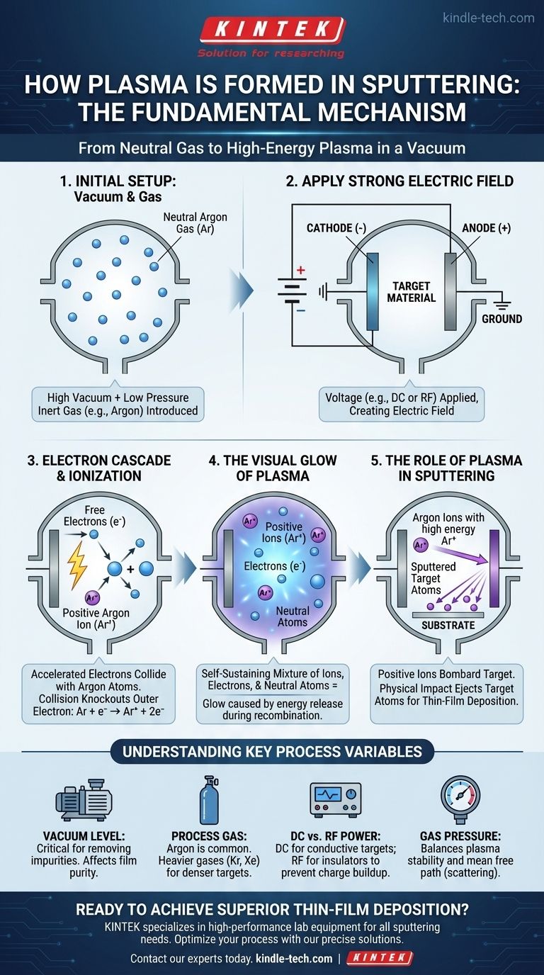
In sputtering, plasma is formed by applying a high-voltage electric field within a vacuum chamber filled with a low-pressure inert gas, typically Argon. This field accelerates free electrons, which then collide with and ionize the gas atoms. This process creates a self-sustaining mixture of positively charged ions, electrons, and neutral gas atoms, which we recognize as plasma.
The generation of plasma is not the end goal of sputtering, but rather the essential intermediate step. Its sole purpose is to create a controlled stream of high-energy ions that act as microscopic projectiles, bombarding a target material to release its atoms for thin-film deposition.
The Fundamental Mechanism: From Gas to Plasma
To truly understand sputtering, you must first understand the precise sequence of events that turns a neutral gas into a working plasma. This happens in a carefully controlled environment.
The Initial Setup: A Vacuum and a Gas
The process begins in a high-vacuum chamber. This vacuum is critical to remove impurities and ensure the sputtered atoms can travel to the substrate without colliding with unwanted air molecules.
An inert process gas, most commonly Argon (Ar), is then introduced into the chamber at a very low pressure.
Applying a Strong Electric Field
A significant voltage difference, often hundreds of volts, is applied between two electrodes. The cathode is negatively charged and holds the "target"—the material you want to deposit.
The anode is typically the chamber wall itself, which is connected to electrical ground. This creates a powerful electric field throughout the gas.
The Electron Cascade
There are always a few free electrons naturally present in the gas. The strong electric field immediately accelerates these negatively charged electrons away from the cathode at high speed.
Ionization Through Collision
As these high-energy electrons travel, they collide with the neutral Argon atoms. If an electron has enough energy, it will knock an electron out of the Argon atom's outer shell.
This collision leaves behind a positively charged Argon ion (Ar+) and a new free electron. This new electron is also accelerated by the field, leading to more collisions and creating a self-sustaining cascade.
The Visual Glow of Plasma
This mixture of positive ions, electrons, and neutral atoms is the plasma. The characteristic glow you see is caused by electrons recombining with ions and dropping to a lower energy state, releasing the excess energy as a photon of light.
The Role of Plasma in the Sputtering Process
Once the plasma is ignited, it becomes the engine that drives the entire deposition process. Its components are precisely manipulated by the electric field to do the required work.
Directing the Ion Bombardment
While the electrons are repelled by the negative cathode, the newly formed positive Argon ions are strongly attracted to it. They accelerate directly toward the target material.
The Sputtering Event
These Argon ions strike the target surface with immense energy. This impact is a purely physical momentum transfer, knocking out, or "sputtering," atoms of the target material.
These ejected target atoms are neutral. They travel in a straight line through the vacuum until they land on your substrate, gradually building up a thin film.
Understanding Key Process Variables
The quality and rate of your deposition are not accidental. They are a direct result of how you control the plasma and its environment. Misunderstanding these can lead to poor results.
The Importance of Vacuum Level
The initial vacuum level is critical. If it's too poor (too much residual gas), your sputtered material will collide with impurities, contaminating your film.
The process pressure (the amount of Argon) is a delicate balance. Too much gas reduces the "mean free path," causing sputtered atoms to collide and scatter before reaching the substrate. Too little gas, and you can't sustain a stable plasma.
The Choice of Sputtering Gas
Argon is the most common choice because it's inert and has a good mass for efficiently sputtering most materials. For denser target materials, heavier inert gases like Krypton (Kr) or Xenon (Xe) can be used to increase the sputtering rate due to their greater momentum.
DC vs. RF Sputtering
For the plasma to be sustained, the target must be electrically conductive. This allows the positive charge from the arriving ions to be neutralized. This is called DC (Direct Current) sputtering.
If your target is an insulator (like an oxide or nitride), positive charge will build up on its surface, repelling the Argon ions and stopping the process. To overcome this, we use RF (Radio Frequency) sputtering, which rapidly alternates the electric field, using the electrons in the plasma to neutralize the charge buildup on each cycle.
Making the Right Choice for Your Goal
Understanding plasma formation allows you to control the sputtering process to achieve your specific deposition objective.
- If your primary focus is depositing a standard metal film: DC sputtering with Argon is the most efficient, cost-effective, and widely used method.
- If your primary focus is depositing an insulating material (e.g., SiO₂, Al₂O₃): RF sputtering is non-negotiable to prevent charge accumulation on the target and sustain the plasma.
- If your primary focus is maximizing deposition rate: You can increase plasma density by raising the power, or for certain materials, switch to a heavier sputtering gas like Krypton.
Mastering the fundamentals of plasma generation is the first and most critical step toward controlling your thin-film deposition outcomes.
Summary Table:
| Key Factor | Role in Plasma Formation | Impact on Sputtering Process |
|---|---|---|
| Vacuum Level | Removes impurities for stable plasma ignition. | Prevents film contamination; ensures clean deposition. |
| Process Gas (e.g., Argon) | Provides atoms to be ionized, forming the plasma. | Affects sputtering rate; heavier gases (Kr, Xe) increase momentum transfer. |
| Electric Field (DC/RF) | Accelerates electrons to ionize gas atoms, sustaining the plasma. | DC for conductive targets; RF for insulating targets to prevent charge buildup. |
| Gas Pressure | Balances plasma stability and mean free path of atoms. | Too high: scattering of sputtered atoms; too low: unstable plasma. |
Ready to Achieve Superior Thin-Film Deposition?
Understanding plasma formation is the foundation of a successful sputtering process. The right equipment is crucial for precise control over vacuum levels, gas flow, and power supply to ensure consistent, high-quality results.
KINTEK specializes in high-performance lab equipment and consumables for all your sputtering needs. Whether you are working with DC sputtering for metals or require advanced RF sputtering for insulating materials, our solutions are designed to enhance your laboratory's efficiency and reliability.
Let us help you optimize your process. Contact our experts today to discuss your specific application and discover how KINTEK can support your research and production goals.
Visual Guide
Related Products
- Spark Plasma Sintering Furnace SPS Furnace
- Vacuum Induction Melting Spinning System Arc Melting Furnace
- Chemical Vapor Deposition CVD Equipment System Chamber Slide PECVD Tube Furnace with Liquid Gasifier PECVD Machine
- Customer Made Versatile CVD Tube Furnace Chemical Vapor Deposition Chamber System Equipment
- HFCVD Machine System Equipment for Drawing Die Nano-Diamond Coating
People Also Ask
- What is the mechanism of SPS process? A Deep Dive into Rapid, Low-Temperature Sintering
- Why are Spark Plasma Sintering (SPS) furnaces or hot presses utilized in the preparation of Li3PS4 solid electrolytes?
- What is the process fundamentals of spark plasma sintering? Achieve Rapid, High-Density Material Consolidation
- What are the fundamentals of spark plasma sintering process? Unlock Rapid, High-Performance Material Consolidation
- What technical advantages does a Spark Plasma Sintering (SPS) furnace offer for LZP ceramics? Enhance Ionic Conductivity