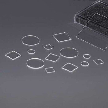
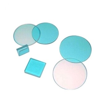
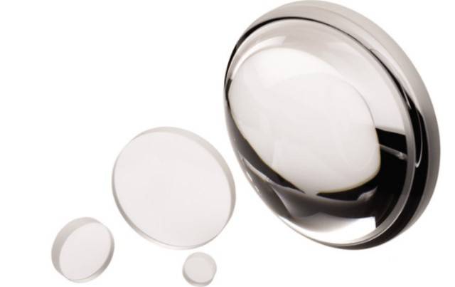
Material Properties of Optical Windows
Transmission and Refractive Index
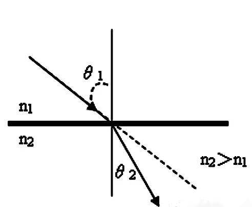
Material properties, including transmission, refractive index, and hardness of the window substrate, play a pivotal role in determining the optimal window choice for various applications. The refractive index is a fundamental parameter that quantifies the reduction in the speed of light as it traverses from a vacuum into an optical medium. This index is particularly crucial as it influences the bending of light rays, which in turn affects the overall optical performance of the window.
For instance, materials with higher refractive indices tend to bend light more sharply, which can be advantageous in certain optical systems where precise light manipulation is required. Conversely, lower refractive indices are often preferred in applications where minimal light distortion is essential, such as in high-resolution imaging systems.
| Property | Description |
|---|---|
| Transmission | The amount of light that passes through the material. |
| Refractive Index | The ratio of the speed of light in a vacuum to the speed of light in the medium. |
| Hardness | The resistance of the material to scratches and abrasions. |
Understanding these properties allows for the selection of optical windows that not only meet the transmission requirements but also ensure the desired level of optical clarity and durability. This holistic approach ensures that the chosen window material aligns perfectly with the specific needs of the application, whether it be in scientific instruments, medical devices, or industrial optics.
Abbe Number and Dispersion
The Abbe number (vd) is a crucial parameter in characterizing the dispersion properties of optical materials, which refers to how the refractive index of a material varies with wavelength. Dispersion is a fundamental property that influences the performance of optical systems, particularly in applications requiring high precision. Materials with low Abbe numbers exhibit high dispersion, meaning their refractive index changes significantly across different wavelengths. This variation can lead to chromatic aberrations, which are color-dependent distortions in images.
Coronal glasses, known for their relatively low dispersion, typically have higher Abbe numbers compared to flint glasses. Flint glasses, on the other hand, are characterized by their higher dispersion and lower Abbe numbers. The difference in Abbe numbers between these two types of glasses is indicative of their respective roles in optical design. For instance, coronal glasses are often preferred in applications where minimizing chromatic aberrations is paramount, such as in high-resolution imaging systems.
Understanding the Abbe number and its implications on dispersion is essential for selecting the appropriate optical material for specific applications. The table below provides a comparison of Abbe numbers for common types of coronal and flint glasses, illustrating the significant difference in their dispersion characteristics.
| Glass Type | Abbe Number (vd) |
|---|---|
| Coronal | 60-85 |
| Flint | 30-55 |
This distinction in Abbe numbers underscores the importance of considering dispersion properties when designing optical systems, ensuring optimal performance and image quality.
Density and Thermal Expansion
The density of the glass plays a pivotal role in the overall weight of the optical assembly. This characteristic is particularly significant when considering the portability and handling requirements of the optical system. For instance, in portable devices, a lower density material can significantly reduce the overall weight, making the equipment more manageable and user-friendly.
The coefficient of thermal expansion (CTE) is another critical parameter that dictates how the dimensions of the glass change with temperature fluctuations. This property is essential for applications where temperature variations are expected, such as in outdoor or industrial settings. A high CTE can lead to dimensional instability, causing the optical window to warp or crack under thermal stress. Therefore, selecting a glass with a CTE that matches the operating temperature range of the application is crucial to ensure long-term performance and reliability.
| Property | Importance |
|---|---|
| Density | Determines the weight of the optical assembly; critical for portability. |
| Thermal Expansion | Affects dimensional stability under temperature changes; vital for durability. |
Understanding these properties allows for the selection of an optical glass plate that not only meets the optical requirements but also ensures mechanical stability and durability across varying environmental conditions.
Knoop Hardness
The Knoop hardness of glass is a critical parameter that quantifies its resistance to indentation. This property is particularly significant in applications where the glass is subjected to mechanical stress or abrasion. Materials exhibiting higher Knoop hardness values are generally less prone to brittleness and can endure greater differential pressures without sustaining damage.
To illustrate, consider a comparison between two types of glass: one with a high Knoop hardness and another with a lower value. The glass with higher Knoop hardness will demonstrate superior durability under conditions of mechanical stress, making it ideal for use in environments where resistance to wear and tear is paramount. This characteristic is particularly advantageous in optical applications where the integrity of the glass surface must be maintained over extended periods.
| Glass Type | Knoop Hardness (HK) | Resistance to Indentation | Brittleness | Differential Pressure Tolerance |
|---|---|---|---|---|
| Type A | 700 | High | Low | High |
| Type B | 400 | Low | High | Low |
In summary, the Knoop hardness of glass serves as an essential metric in assessing its suitability for various optical applications, particularly those involving mechanical stress or the need for long-term surface integrity.
Optical Surface Specifications
Surface Quality and Scratch Specifications
The surface quality of an optical window is a critical parameter that evaluates the presence of surface defects, which can arise during the manufacturing or processing stages. These defects, if not controlled, can significantly impact the performance and reliability of the optical system. Surface quality is typically quantified using the scratch and dig (S/D) specifications, as outlined in the American Standard MIL-PRF-13830B.
To better understand these specifications, it's essential to delve into the two primary components: scratches and digs. Scratches refer to linear defects that can be caused by mechanical abrasion, while digs are localized depressions or pits resulting from impact or excessive pressure. The scratch specification, often denoted as "80-50," indicates the allowable size and number of scratches on the surface. For instance, "80" signifies that scratches up to 80 microns in length are permissible, and "50" indicates the maximum width of these scratches.
| Specification | Description | Impact on Performance |
|---|---|---|
| Scratches | Linear defects up to 80 microns in length and 50 microns in width | Can scatter light, reducing optical clarity and efficiency |
| Digs | Localized depressions or pits | Can cause localized stress, leading to potential failure under pressure |
These specifications are not arbitrary but are based on rigorous testing and empirical data that correlate defect size with optical performance. Ensuring compliance with these standards is crucial for maintaining the integrity of the optical window and ensuring optimal performance in various applications.
Surface Flatness
Surface flatness is a critical parameter in the evaluation of optical windows, quantifying the deviation of a window's surface from an ideal, perfectly flat state. This metric is essential for maintaining the integrity and performance of optical systems, as even minor deviations can significantly impact the quality of transmitted images and the efficiency of light transmission.
The measurement of surface flatness typically involves the use of an optical plane, a sophisticated tool that employs precise optical principles to detect and quantify surface irregularities. By comparing the test piece to a reference plane, the optical plane can identify deviations with high accuracy, providing a detailed map of the surface's flatness.
To better understand the significance of surface flatness, consider the following table:
| Surface Flatness Grade | Maximum Deviation (μm) | Impact on Optical Systems |
|---|---|---|
| Grade 1 | 0.1 | Minimal impact, suitable for high-precision applications |
| Grade 2 | 0.5 | Acceptable for most optical systems, slight degradation in image quality |
| Grade 3 | 1.0 | Noticeable degradation in image quality, suitable for low-precision applications |
In summary, surface flatness is a non-negotiable specification for optical windows, influencing the overall performance and reliability of optical systems. The use of advanced measurement tools like the optical plane ensures that these specifications are met with the utmost precision, safeguarding the functionality of the optical components in various applications.
Transmitted Wavefront Error
Transmitted wavefront error (TWFE) is a critical parameter in the evaluation of optical windows, particularly in systems where image quality is paramount. This error arises from a combination of factors, including surface errors, refractive index inhomogeneities, and mechanical stresses on the window. Surface errors can be attributed to imperfections in the manufacturing process, such as scratches, pits, or irregularities that deviate from the ideal flat or curved surface. Refractive index inhomogeneities, on the other hand, occur when the material of the window is not uniformly dense, leading to variations in the speed of light transmission. Mechanical stresses, often induced during installation or environmental changes, can also contribute to TWFE by causing the window to deform slightly.
The impact of TWFE is significant in image-forming systems, where even minor distortions can lead to a noticeable degradation in image quality. For instance, in high-resolution imaging systems, such as those used in microscopy or astronomy, TWFE can result in blurred or distorted images, reducing the system's overall performance. This degradation can manifest as a loss of contrast, increased noise, or the appearance of ghost images, all of which can hinder the accuracy and effectiveness of the imaging process.
To mitigate TWFE, manufacturers employ various techniques, including rigorous surface polishing, stress-relief treatments, and the use of materials with highly uniform refractive indices. Additionally, advanced metrology tools, such as interferometers, are used to measure and quantify TWFE, allowing for precise adjustments and improvements in the manufacturing process. By addressing these factors, it is possible to significantly reduce TWFE and thereby enhance the performance of optical systems.
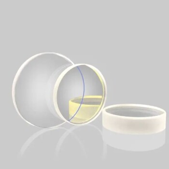
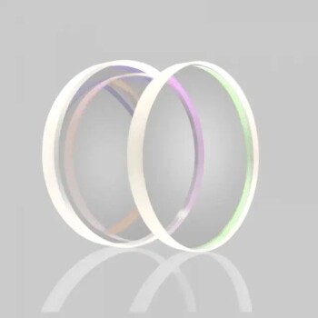
Anti-Reflection (AR) Coating
Purpose and Benefits
Anti-Reflection (AR) coatings are meticulously applied to optical windows to optimize transmission within the intended wavelength spectrum. These coatings serve a dual purpose: they not only boost the overall efficiency of the optical system but also enhance the visual clarity by minimizing unwanted artifacts such as ghost images and reducing light scattering.
By strategically increasing transmission, AR coatings ensure that more light passes through the optical window, thereby improving the overall performance of the system. This enhancement is particularly crucial in applications where high contrast is necessary, such as in microscopy or imaging systems, where even minor reflections can significantly degrade image quality.
Moreover, the elimination of ghost images through AR coatings contributes to a cleaner and more precise visual output. This is achieved by reducing the internal reflections within the optical system, which can otherwise create secondary images that interfere with the primary image. As a result, the clarity and sharpness of the final image are significantly improved, making AR coatings indispensable in high-precision optical applications.
Specification and Application
When specifying an AR coating for a specific application, it is crucial to first fully understand the full spectral range of the system. The spectral range refers to the range of wavelengths that the optical system is designed to operate within. This understanding is essential because the performance of the AR coating is optimized for a particular wavelength range.
Using coatings at wavelengths outside of the designed range can lead to several issues. For instance, the coating may not effectively reduce reflections, leading to increased light loss. This can degrade the overall performance of the system, affecting parameters such as transmission efficiency, contrast, and the elimination of ghost images. Moreover, improper use of AR coatings can introduce unwanted interference patterns, further compromising the clarity and quality of the optical system's output.
To avoid these pitfalls, it is recommended to consult with experts or use advanced simulation tools to ensure that the AR coating is tailored to the specific spectral requirements of the application. This approach not only maximizes the benefits of the AR coating but also ensures that the optical system performs optimally across its intended range of wavelengths.
Related Products
- CVD Diamond Optical Windows for Lab Applications
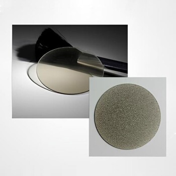
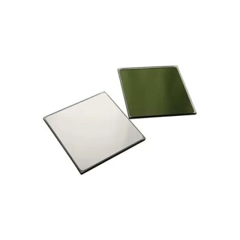
- Optical Window Glass Substrate Wafer Sheets Zinc Sulfide ZnS Window
- Optical Window Glass Substrate Wafer Barium Fluoride BaF2 Substrate Window
- Optical Window Glass Substrate Wafer Single Double Sided Coated K9 Quartz Sheet
- Optical Window Glass Substrate Wafer CaF2 Substrate Window Lens