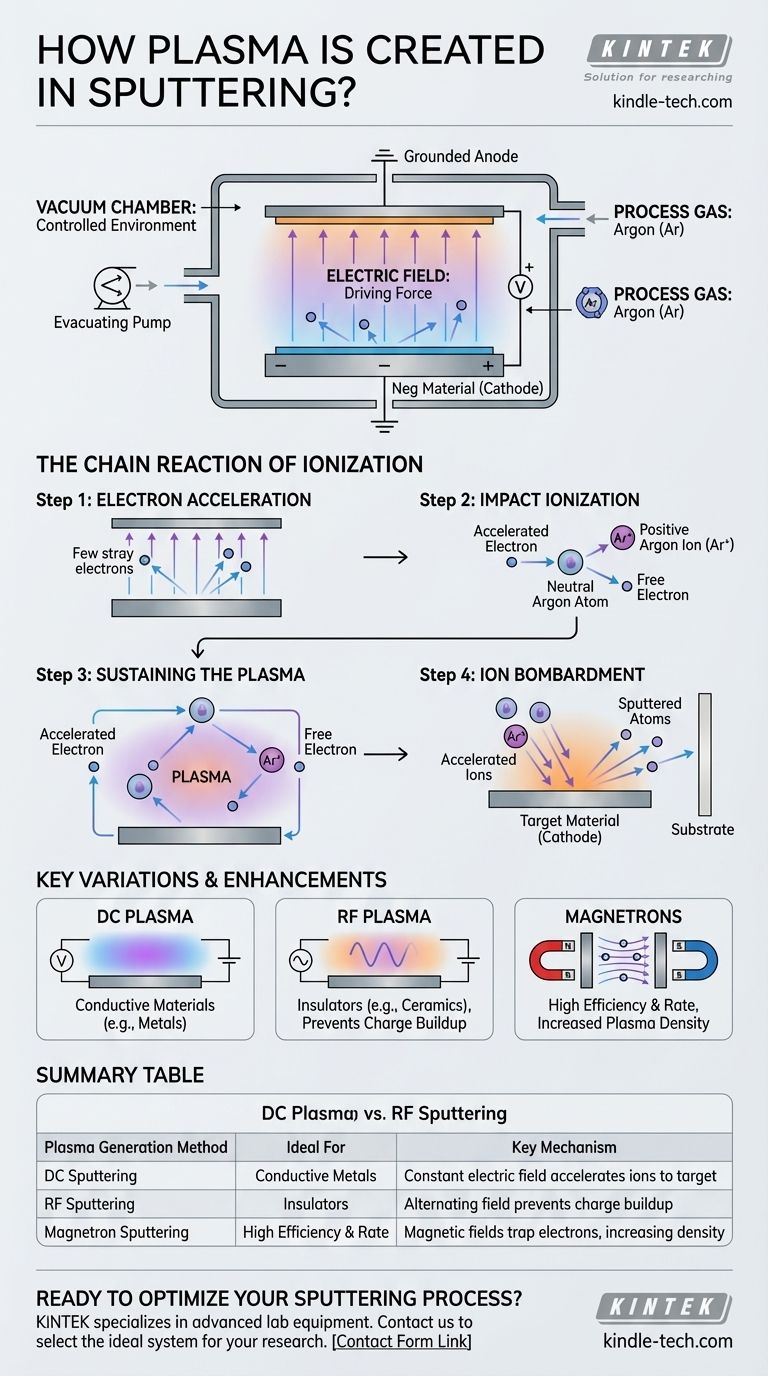
At its core, plasma for sputtering is created by applying a strong electric field to a low-pressure inert gas inside a vacuum chamber. This high voltage energizes free electrons, which then collide with gas atoms, knocking off more electrons in a chain reaction. This process, known as ionization, transforms the neutral gas into an energetic state of matter consisting of positive ions and free electrons—the plasma.
The crucial insight is that plasma generation is not a separate step but an integral part of the sputtering mechanism. The same electric field that creates the plasma by ionizing the gas is also responsible for accelerating those newly formed ions into the target material, initiating the physical sputtering process.
The Fundamental Recipe for Sputtering Plasma
To understand how plasma is generated, we must first look at the three essential ingredients required to set the stage within the sputtering chamber.
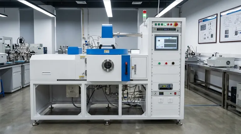
The Vacuum Chamber: Creating a Controlled Environment
The entire process begins by evacuating a chamber to a high vacuum. This removes air and other molecular contaminants, ensuring that the deposited film is pure and that the subsequent process is stable and predictable.
The Process Gas: Providing the Raw Material
Once a vacuum is achieved, the chamber is backfilled with a small, controlled amount of a high-purity inert gas, most commonly argon (Ar). This gas is chemically non-reactive and serves as the source material that will be converted into plasma.
The Electric Field: The Driving Force
A large voltage differential is applied between two electrodes: the cathode, which is the target material you want to sputter, and the anode, which is typically the substrate or the chamber walls. A strong negative voltage is applied specifically to the target.
The Chain Reaction of Ionization
With the environment set, the application of voltage triggers a rapid, self-sustaining cascade that forms the plasma, often visible as a characteristic glow discharge.
Step 1: Electron Acceleration
There are always some stray free electrons present in the chamber. The strong electric field immediately accelerates these negatively charged electrons away from the negative target (cathode) and toward the anode.
Step 2: Impact Ionization
As these electrons gain kinetic energy, they collide with the neutral, low-pressure argon atoms. If an electron has sufficient energy, it will knock an electron out of the argon atom's orbital shell.
This collision results in two key products: a positively charged argon ion (Ar+) and a second free electron.
Step 3: Sustaining the Plasma
This process creates a feedback loop. The original electron and the newly freed electron are both accelerated by the electric field, leading to more collisions and creating more positive ions and electrons. This cascade of ionization is what creates and sustains the plasma.
Step 4: Ion Bombardment
The purpose of this entire process is to create the argon ions. Because they are positively charged, these ions are aggressively accelerated by the electric field in the opposite direction of the electrons—directly toward the negatively charged target material. Their high-energy impact is what physically dislodges target atoms, "sputtering" them onto the substrate.
Key Variations and Enhancements
While the basic principle remains the same, different methods are used to generate and control the plasma depending on the material being sputtered.
DC vs. RF Plasma Excitation
For sputtering electrically conductive materials like metals, a simple Direct Current (DC) voltage is sufficient. However, if the target is an electrical insulator (e.g., a ceramic), a positive charge will build up on its surface, repelling the argon ions and quickly stopping the process.
To overcome this, Radio Frequency (RF) sputtering is used. It rapidly alternates the electric field, preventing charge accumulation and allowing for the effective sputtering of non-conductive materials.
The Role of Magnetrons
Modern sputtering systems almost always use magnetron sputtering. This technique places strong magnets behind the target. The magnetic field traps the highly mobile electrons in a confined path near the target's surface, dramatically increasing the probability of collision with argon atoms. This creates a much denser plasma at lower pressures, resulting in a significantly more efficient and faster sputtering process.
Making the Right Choice for Your Process
Understanding how plasma is generated allows you to better control the deposition of your thin film. The method you use is dictated by your target material and desired efficiency.
- If your primary focus is sputtering a metal (conductive target): A standard DC power supply provides the constant electric field needed to create and sustain the plasma for efficient deposition.
- If your primary focus is sputtering a ceramic or insulator (non-conductive target): RF power is essential to alternate the electric field, which prevents charge buildup on the target and keeps the plasma active.
- If your primary focus is maximizing deposition rate and efficiency: A magnetron system is the industry standard, as it uses magnetic fields to enhance ionization and create a denser, more effective plasma.
Ultimately, creating plasma for sputtering is a precise process of using an electric field to convert a neutral gas into an energetic tool for carving atoms from a target.
Summary Table:
| Plasma Generation Method | Ideal For | Key Mechanism |
|---|---|---|
| DC Sputtering | Conductive Metals (e.g., Au, Al) | Constant electric field accelerates ions to target |
| RF Sputtering | Insulators (e.g., Ceramics, Oxides) | Alternating field prevents charge buildup on target |
| Magnetron Sputtering | High Efficiency & Rate | Magnetic fields trap electrons, increasing plasma density |
Ready to Optimize Your Sputtering Process?
Whether you are depositing conductive metals or insulating ceramics, choosing the right plasma generation method is critical for high-quality thin films. KINTEK specializes in advanced lab equipment and consumables, providing tailored sputtering solutions that enhance deposition efficiency and film purity.
Let our experts help you select the ideal system for your research or production needs. Contact us today to discuss how our reliable sputtering equipment can accelerate your project's success!
Visual Guide
Related Products
- Spark Plasma Sintering Furnace SPS Furnace
- Inclined Rotary Plasma Enhanced Chemical Vapor Deposition PECVD Equipment Tube Furnace Machine
People Also Ask
- What is the theory of spark plasma sintering? A Guide to Rapid, Low-Temperature Densification
- What is the pressure for spark plasma sintering? A Guide to Optimizing SPS Parameters
- What technical advantages does a Spark Plasma Sintering (SPS) furnace offer for LZP ceramics? Enhance Ionic Conductivity
- What is SPS sintering method? A Guide to High-Speed, High-Performance Material Fabrication
- Why are Spark Plasma Sintering (SPS) furnaces or hot presses utilized in the preparation of Li3PS4 solid electrolytes?

