At its core, mold tool design is the highly specialized engineering discipline of creating the blueprint for a tool—the mold—that will shape molten material into a finished part. It is a complex process that blends physics, material science, and mechanical engineering to ensure that thousands or millions of parts can be produced with exceptional accuracy and consistency.
Mold tool design is not simply about creating a negative space for a part. It is the science of controlling the flow of material, managing heat, and enabling the efficient, repeatable production of a high-quality product. A well-designed tool is the foundation of successful mass production.
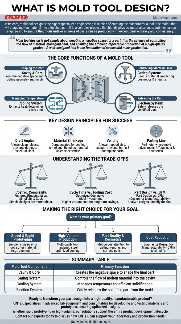
The Core Functions of a Mold Tool
A production mold is far more than a simple container. It is an intricate machine with several interdependent systems, each of which must be designed with precision.
The Cavity and Core: Shaping the Part
The cavity and core are the two halves of the mold that come together to form the negative space of the final part. The design of these surfaces dictates the part's final geometry and surface finish.
The Gating System: Controlling Material Flow
This is the network of channels that directs the molten plastic from the injection molding machine's nozzle into the cavity. The gate's size, type, and location are critical decisions that directly impact the part's cosmetic appearance and structural integrity.
The Cooling System: Managing Temperature
Once the cavity is filled, the part must cool and solidify at a controlled rate. The cooling system consists of channels drilled through the mold through which a fluid (usually water) circulates to extract heat. Efficient cooling is the single largest factor in determining cycle time and profitability.
The Ejection System: Releasing the Part
After the part has solidified, the mold opens and an ejection system—typically a series of pins or plates—pushes the finished part out of the cavity. This system must be designed to eject the part without causing damage or blemishes.
Key Design Principles for Success
The complexity mentioned in the reference material arises from balancing numerous factors that can make or break a project. A successful mold design is a masterclass in managing these variables.
Draft Angles
Virtually no surface on a plastic part can be perfectly perpendicular to the direction the mold opens. A slight angle, known as a draft angle, must be applied to allow the part to release cleanly from the mold during ejection. Insufficient draft causes scuffing, drag marks, and can damage the part or the tool itself.
Material Shrinkage
Every plastic shrinks as it cools. Mold tool designers must be experts in material science, calculating the specific shrinkage rate of the chosen plastic and making the mold cavity slightly larger than the desired final part dimensions to compensate.
Venting
As molten plastic rushes into the cavity, the air that was previously there must have a way to escape. Vents are minuscule channels (often just a few thousandths of an inch deep) ground into the mold's parting line that allow air to exit but are too small for the plastic to flow through. Poor venting leads to trapped air, resulting in incomplete parts or burn marks.
Parting Line
The parting line is the perimeter where the two halves of the mold meet. The placement of this line is a critical decision. It affects the tool's cost, how the part looks cosmetically, and which features require draft.
Understanding the Trade-offs
Effective mold tool design is an exercise in balancing competing priorities. There is rarely a single "perfect" solution, only an optimal one for a specific goal.
Cost vs. Complexity
Features like undercuts or side-actions (which allow for molding complex geometries like clips or side holes) dramatically increase the complexity and cost of a tool. A key part of the design process is to achieve the desired part function with the simplest, most robust tool design possible.
Cycle Time vs. Tooling Cost
A mold with a highly optimized cooling system may cost more upfront to build. However, if that design shaves even a few seconds off the cycle time, the savings in production cost over hundreds of thousands of parts will far outweigh the initial investment.
Part Design vs. Manufacturability
The most significant factor influencing tool design is the design of the part itself. The principle of Design for Manufacturability (DFM) involves analyzing the part design early to identify and correct features—like unnecessarily thick walls or a lack of draft—that would complicate the mold and increase costs.
Making the Right Choice for Your Goal
The objective of mold tool design changes based on the project's primary goal. Understanding this allows you to prioritize the right aspects.
- If your primary focus is speed and rapid prototyping: Opt for a simpler, single-cavity tool made from a softer material like aluminum to reduce machining time and cost.
- If your primary focus is high-volume production: Invest in a multi-cavity tool made from hardened steel with a highly optimized cooling system to maximize output and minimize per-part cost.
- If your primary focus is part quality and cosmetics: Pay meticulous attention to the gate location, venting, and the polish on the cavity and core surfaces.
- If your primary focus is cost reduction: Emphasize Design for Manufacturability (DFM) in the part design phase to simplify the tool and eliminate complex, expensive mechanisms.
Ultimately, understanding mold tool design transforms it from a simple manufacturing step into a strategic asset for creating a successful product.
Summary Table:
| Mold Tool Component | Primary Function |
|---|---|
| Cavity & Core | Creates the negative space to shape the final part |
| Gating System | Controls the flow of molten material into the cavity |
| Cooling System | Manages temperature for efficient solidification |
| Ejection System | Safely releases the solidified part from the mold |
Ready to transform your part design into a high-quality, manufacturable product?
The principles of mold tool design are critical for success, but implementing them requires deep expertise and precision equipment. At KINTEK, we specialize in providing the advanced lab equipment and consumables necessary for developing and testing materials and prototypes, ensuring your designs are optimized for manufacturing.
Whether you're focused on rapid prototyping or high-volume production, our solutions support the entire product development lifecycle. Let us help you achieve exceptional accuracy, consistency, and efficiency.
Contact our experts today to discuss how KINTEK can support your laboratory and production needs!
Visual Guide