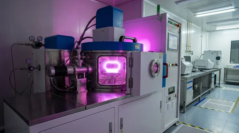
In essence, plasma for sputtering is created by applying a strong electric field to a low-pressure gas, typically an inert gas like argon. This electrical energy is so powerful that it strips electrons from the gas atoms, transforming the neutral gas into an energized, ionized state known as plasma. This plasma—a mixture of positive ions, free electrons, and neutral atoms—is the critical medium for the sputtering process.
The creation of plasma is not a chemical reaction but a physical transformation. By energizing a process gas within a vacuum chamber, you create a self-sustaining "electron avalanche" that ionizes the gas, providing the charged ions needed to bombard the target material.
The Fundamental Principle: Gas Ionization
To understand how plasma is generated, you must first understand the process of ionization. Sputtering does not happen in a true vacuum; it requires a specific gas at a very low pressure to act as the medium.
Starting with an Inert Gas
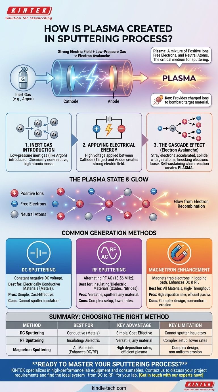
The process begins by introducing an inert gas, most commonly argon (Ar), into the vacuum chamber. Argon is chosen because it is chemically non-reactive and has a relatively high atomic mass, making it effective for physically bombarding a target without causing unwanted chemical reactions.
Applying Electrical Energy
A high voltage is applied between two electrodes inside the chamber: the cathode (which holds the target material you want to deposit) and the anode (often the chamber walls or a dedicated electrode). This creates a powerful electric field.
The Cascade Effect (Electron Avalanche)
There are always a few stray free electrons present in the chamber from cosmic rays or natural thermal energy. The electric field accelerates these free electrons to very high speeds.
When a high-energy electron collides with a neutral argon atom, it can knock another electron loose from that atom. The result is one positive argon ion (Ar+) and two free electrons. These two electrons are then accelerated by the electric field, striking and ionizing two more argon atoms, which results in four electrons, and so on. This rapid, self-sustaining chain reaction is known as a cascade effect or an electron avalanche, and it is what causes the gas to rapidly transform into plasma.
The Plasma State and Glow
The resulting plasma is a quasi-neutral "soup" of positive ions and free electrons. The characteristic glow seen during sputtering occurs when a free electron recombines with a positive ion. As the electron falls into a lower energy state, the excess energy is released as a photon of light, producing the visible glow.
Common Methods for Generating the Electric Field
The "electric field" is not a one-size-fits-all concept. The method used to generate it is a defining characteristic of the sputtering system and is chosen based on the material being deposited.
DC (Direct Current) Sputtering
This is the simplest method. A constant negative DC voltage is applied to the target material (the cathode). This steadily attracts the positive argon ions, which bombard the target. It is straightforward and effective, but it only works if the target material is electrically conductive.
RF (Radio Frequency) Sputtering
For sputtering insulating (dielectric) materials like oxides or nitrides, DC sputtering will not work. A positive charge would quickly build up on the insulator's surface, repelling the argon ions and stopping the process.
Instead, an RF alternating current (AC), typically at 13.56 MHz, is applied. During one half-cycle, the target is negative, attracting ions for sputtering. During the other half-cycle, it becomes positive, attracting the free electrons from the plasma to neutralize the charge buildup. This rapid switching allows for the continuous sputtering of non-conductive materials.
Magnetron Enhancement
Modern systems almost always use magnetron sputtering. This method enhances both DC and RF techniques by placing strong magnets behind the cathode target. The magnetic field traps the highly mobile electrons in a looping path directly in front of the target.
This electron trap dramatically increases the probability of an electron colliding with and ionizing a neutral argon atom, creating a much denser, more intense plasma right where it is needed most. This results in significantly higher sputtering rates and more efficient processing.
Understanding the Trade-offs
Choosing a plasma generation method involves clear trade-offs between simplicity, material compatibility, and efficiency.
DC Sputtering: Simple but Limited
DC sputtering is a robust and cost-effective method for depositing metals and other conductive materials. However, its inability to handle insulating targets is a major limitation, and it can be prone to arcing.
RF Sputtering: Versatile but Complex
RF sputtering is the workhorse for research and depositing complex material stacks because it can sputter literally any material. This versatility comes at the cost of more expensive and complex power supplies and matching networks, and generally lower deposition rates compared to DC magnetron.
Magnetron Enhancement: Efficiency at a Cost
Adding magnets to the system (magnetron sputtering) is the industry standard for high-throughput manufacturing. It dramatically increases deposition rates and allows for lower pressure operation. The trade-off is a more complex cathode design and non-uniform erosion of the target material (known as a "racetrack").
Making the Right Choice for Your Goal
The method used to create plasma is directly tied to the material you need to deposit and the efficiency you require.
- If your primary focus is depositing a simple conductive film: Standard DC magnetron sputtering offers the best combination of speed and cost-effectiveness.
- If your primary focus is depositing an insulating or dielectric material: RF magnetron sputtering is the necessary and correct choice.
- If your primary focus is maximum deposition rate for industrial production: High-power DC or pulsed magnetron sputtering systems are engineered for this exact purpose.
Ultimately, mastering the sputtering process begins with understanding that controlling the creation and confinement of the plasma gives you control over the final film.
Summary Table:
| Plasma Generation Method | Best For Material Type | Key Advantage | Key Limitation |
|---|---|---|---|
| DC Sputtering | Electrically Conductive (e.g., Metals) | Simple, Cost-Effective | Cannot sputter insulating materials |
| RF Sputtering | Insulating/Dielectric (e.g., Oxides, Nitrides) | Versatile; sputters any material | Complex setup, lower deposition rates |
| Magnetron Sputtering | All Materials (enhances DC/RF) | High deposition rates, efficient plasma | Complex design, non-uniform target erosion |
Ready to Master Your Sputtering Process?
Choosing the right plasma generation method is critical for achieving high-quality, uniform thin films. Whether you are developing new semiconductor devices, advanced optical coatings, or durable protective layers, the experts at KINTEK are here to help.
We specialize in providing high-performance lab equipment and consumables for all your sputtering needs. Our team can guide you to the ideal system—from robust DC magnetron for metals to versatile RF systems for ceramics—ensuring efficiency, precision, and reliability for your laboratory.
Contact us today to discuss your project requirements and discover how KINTEK's solutions can enhance your research and production outcomes. Get in touch with our experts now!
Visual Guide
Related Products
- Spark Plasma Sintering Furnace SPS Furnace
- Vacuum Induction Melting Spinning System Arc Melting Furnace
- Chemical Vapor Deposition CVD Equipment System Chamber Slide PECVD Tube Furnace with Liquid Gasifier PECVD Machine
- Customer Made Versatile CVD Tube Furnace Chemical Vapor Deposition Chamber System Equipment
- HFCVD Machine System Equipment for Drawing Die Nano-Diamond Coating
People Also Ask
- What is the theory of spark plasma sintering? A Guide to Rapid, Low-Temperature Densification
- Why are Spark Plasma Sintering (SPS) furnaces or hot presses utilized in the preparation of Li3PS4 solid electrolytes?
- What technical advantages does a Spark Plasma Sintering (SPS) furnace offer for LZP ceramics? Enhance Ionic Conductivity
- What is the mechanism of SPS process? A Deep Dive into Rapid, Low-Temperature Sintering
- What is the difference between spark plasma sintering and flash sintering? A Guide to Advanced Sintering Methods