In sputtering, plasma is generated by applying a high-voltage electrical discharge between two electrodes inside a vacuum chamber filled with a low-pressure inert gas, typically Argon. This strong electric field accelerates free electrons, which then collide with the neutral gas atoms. These collisions are energetic enough to knock electrons off the atoms, creating a self-sustaining population of positive ions and free electrons that constitutes the plasma.
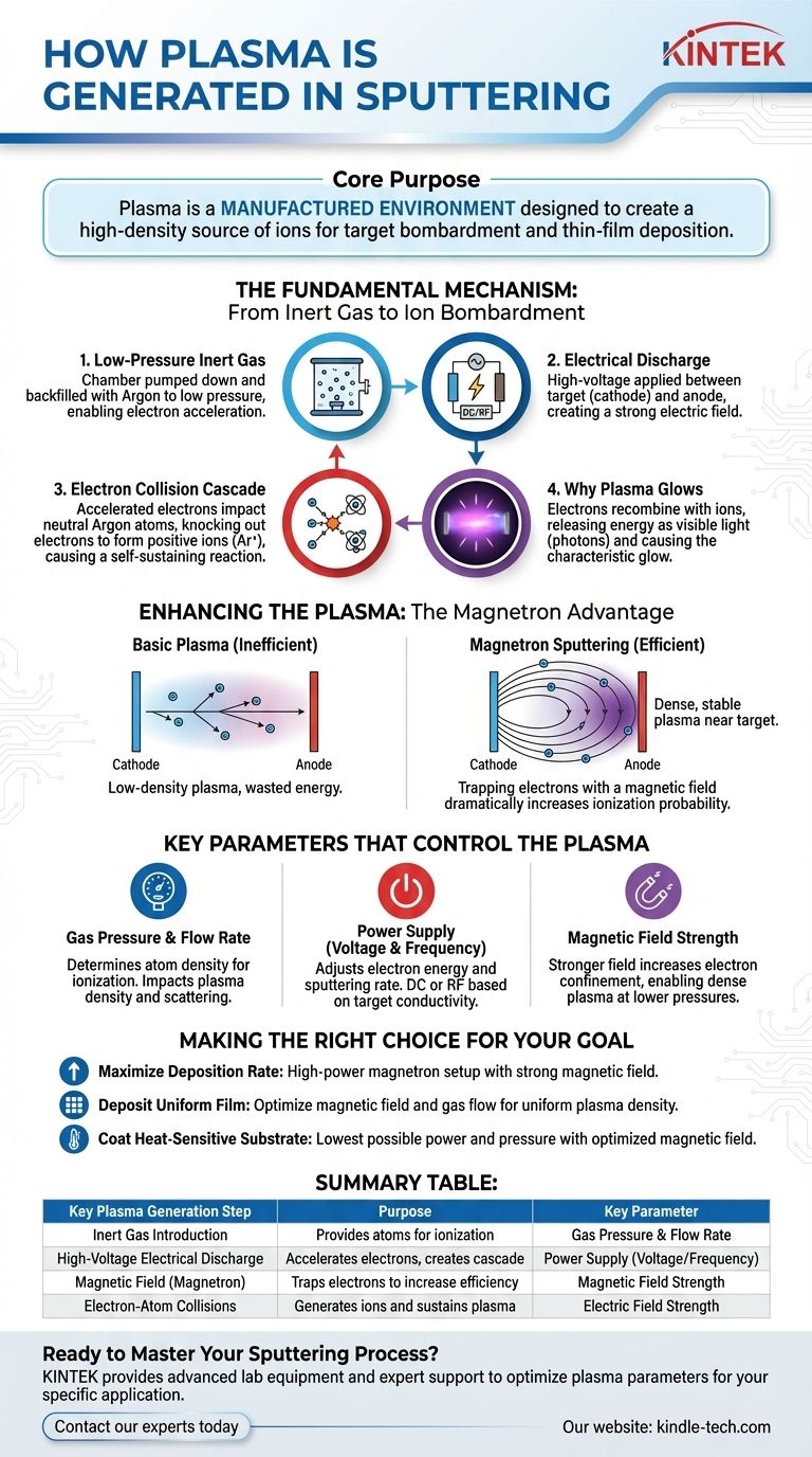
The core purpose of generating plasma in sputtering is not incidental; it is the fundamental engine of the process. The plasma is a manufactured environment designed specifically to create a high-density source of ions that can then be accelerated to bombard a target and physically eject material for thin-film deposition.
The Fundamental Mechanism: From Inert Gas to Ion Bombardment
To understand how sputtering works, you must first understand the step-by-step process of creating its essential ingredient: the plasma. It is a controlled chain reaction that transforms a stable gas into an energetic, reactive state.
The Starting Point: A Low-Pressure Inert Gas
The entire process begins by pumping down a vacuum chamber and backfilling it with an inert gas, like Argon, to a very low pressure. This low pressure is critical because it allows electrons and ions to travel a significant distance before colliding, enabling them to gain enough energy from the electric field.
Applying the Electrical Discharge
A high voltage, either Direct Current (DC) or Radio Frequency (RF), is applied between two electrodes. The material you wish to deposit, known as the target, acts as the cathode (negative electrode), while the substrate holder or chamber walls can act as the anode (positive electrode).
The Electron Collision Cascade
A few stray electrons, always present in any system, are accelerated by the strong electric field toward the anode. As they gain speed and energy, they collide with neutral Argon atoms. If the collision is energetic enough, it knocks an electron out of the Argon atom, resulting in two free electrons and one positively charged Argon ion (Ar+). These two electrons are then accelerated, leading to more collisions and creating a rapid, self-sustaining cascade that quickly ionizes the gas.
Why the Plasma Glows
The characteristic glow of the plasma is a direct result of this high-energy environment. It occurs when a free electron recombines with a positive ion, causing the ion to return to a lower, more stable energy state. The excess energy from this transition is released in the form of a photon of light, producing the visible glow.
Enhancing the Plasma: The Magnetron Advantage
While a simple DC discharge can create plasma, it is often inefficient. Modern sputtering systems almost universally use magnets to enhance and control the plasma, a technique known as magnetron sputtering.
The Inefficiency of Basic Plasma
In a simple setup, many electrons can travel directly from the cathode (target) to the anode without ever colliding with a gas atom. This represents wasted energy and results in a low-density plasma, leading to slow and inefficient sputtering.
Trapping Electrons with a Magnetic Field
Magnetron sputtering places a strong magnetic field directly behind the target. This magnetic field is oriented parallel to the target surface. Because electrons are charged particles, they are forced to follow a spiral path along these magnetic field lines instead of moving directly to the anode.
The Impact of Electron Trapping
This spiraling path dramatically increases the travel distance of electrons near the target surface. A longer path means a drastically higher probability of colliding with and ionizing the neutral Argon atoms. This creates a very dense, stable plasma precisely where it is most needed—directly in front of the target—leading to a much higher sputtering rate even at lower gas pressures.
Key Parameters That Control the Plasma
The characteristics of the plasma are not fixed; they are carefully controlled by several key parameters. Adjusting these variables directly impacts the stability of the plasma, the rate of deposition, and the quality of the final thin film.
Gas Pressure and Flow Rate
The pressure of the inert gas determines the density of atoms available for ionization. Higher pressure can create a denser plasma but may also cause sputtered atoms to be scattered before they reach the substrate, reducing the deposition rate.
Power Supply (Voltage and Frequency)
Increasing the applied power (voltage) provides more energy to the electrons, which in turn increases the ionization rate and the energy of the ions striking the target. This directly increases the sputtering rate. The choice between DC and RF power depends on whether the target material is electrically conductive or insulating.
Magnetic Field Strength
In magnetron sputtering, a stronger magnetic field provides better electron confinement near the target. This allows a dense and stable plasma to be maintained at lower pressures, which is often desirable for creating higher-quality films.
Making the Right Choice for Your Goal
Controlling the plasma generation process is central to achieving your desired deposition outcome. The optimal parameters are always a function of your specific material and application requirements.
- If your primary focus is maximizing deposition rate: Utilize a high-power magnetron sputtering setup with a strong magnetic field to create the densest possible plasma in front of the target.
- If your primary focus is depositing a uniform film: Ensure your magnetic field and gas flow are designed to produce a uniform plasma density across the entire surface of the sputtering target.
- If your primary focus is coating a heat-sensitive substrate: Operate at the lowest possible power and pressure while using an optimized magnetic field to maintain a stable, efficient plasma, thereby minimizing substrate heating.
Ultimately, mastering the plasma is mastering the art of sputtering itself.
Summary Table:
| Key Plasma Generation Step | Purpose | Key Parameter |
|---|---|---|
| Inert Gas Introduction (e.g., Argon) | Provides atoms for ionization | Gas Pressure & Flow Rate |
| High-Voltage Electrical Discharge (DC/RF) | Accelerates electrons to create ionization cascade | Power Supply (Voltage/Frequency) |
| Magnetic Field (Magnetron Sputtering) | Traps electrons to increase ionization efficiency | Magnetic Field Strength |
| Electron-Atom Collisions | Generates positive ions (Ar+) and sustains plasma | Electric Field Strength |
Ready to Master Your Suttering Process?
Understanding plasma generation is the first step to achieving precise, high-quality thin films. KINTEK specializes in advanced lab equipment and consumables, providing the reliable sputtering systems and expert support your laboratory needs to optimize plasma parameters for your specific application—whether you prioritize deposition rate, film uniformity, or substrate safety.
Contact our experts today to discuss how our solutions can enhance your research and production capabilities.
Visual Guide
Related Products
- Spark Plasma Sintering Furnace SPS Furnace
- Vacuum Induction Melting Spinning System Arc Melting Furnace
- Chemical Vapor Deposition CVD Equipment System Chamber Slide PECVD Tube Furnace with Liquid Gasifier PECVD Machine
- Customer Made Versatile CVD Tube Furnace Chemical Vapor Deposition Chamber System Equipment
People Also Ask
- What is the theory of spark plasma sintering? A Guide to Rapid, Low-Temperature Densification
- What is the difference between spark plasma sintering and flash sintering? A Guide to Advanced Sintering Methods
- What are the advantages of CAMI/SPS for W-Cu composite preparation? Reduce cycles from hours to seconds.
- What is the process fundamentals of spark plasma sintering? Achieve Rapid, High-Density Material Consolidation
- What are the fundamentals of spark plasma sintering process? Unlock Rapid, High-Performance Material Consolidation


