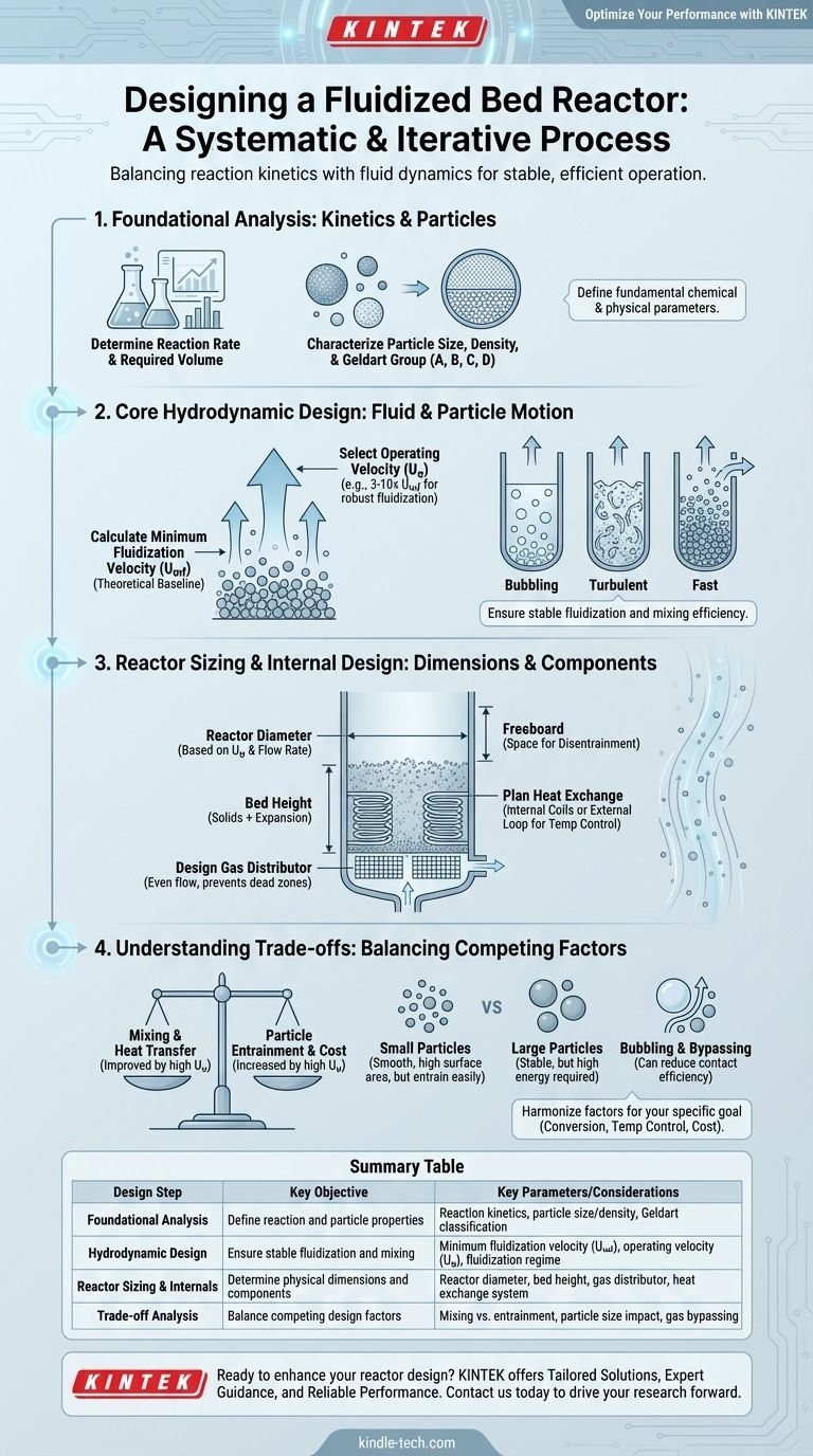
Designing a fluidized bed reactor is a systematic process that integrates reaction kinetics, particle properties, and fluid dynamics. The core steps involve first determining the required reaction volume from kinetic data, then selecting a particle size and calculating the minimum fluidization velocity. From there, you establish an operating velocity, calculate the reactor diameter and bed height, and finally, design the gas distributor and heat exchange systems.
The design of a fluidized bed reactor is not a linear checklist but an iterative process. The central challenge is balancing the competing demands of reaction kinetics (how fast the reaction occurs) and fluid dynamics (how the particles and gas behave) to achieve stable and efficient operation.
Foundational Analysis: Kinetics and Particle Selection
Before any physical design can begin, you must understand the fundamental chemical and physical parameters of your system. These initial choices will dictate all subsequent engineering decisions.
Determine the Reaction Kinetics
The entire purpose of the reactor is to facilitate a chemical reaction. You must first know the reaction rate equation, which describes how quickly reactants are converted into products.
This data, typically obtained from laboratory-scale experiments, is used to calculate the required volume of solid catalyst or reactant needed to achieve your desired production output and conversion.
Characterize the Solid Particles
The behavior of the fluidized bed is entirely dependent on the properties of the solid particles. You must characterize their mean particle size, size distribution, and particle density.
These properties are used to classify the powder according to the Geldart classification (Groups A, B, C, D), which predicts its fluidization behavior. For example, Group A powders fluidize smoothly before bubbling, while Group B powders begin bubbling immediately at the minimum fluidization velocity.
Core Hydrodynamic Design
Hydrodynamics is the study of the fluid (gas or liquid) and solid particle motion. This is the heart of FBR design, as it determines the mixing, contact efficiency, and stability of the reactor.
Calculate Minimum Fluidization Velocity (Umf)
The minimum fluidization velocity (Umf) is the superficial gas velocity at which the drag force exerted by the upward-flowing gas first equals the weight of the particles. At this point, the solid bed begins to behave like a fluid.
This is a theoretical baseline calculated using equations (like the Ergun equation) that incorporate particle size, particle density, and fluid properties. Operation must always occur above this velocity.
Select the Operating Velocity (Uo)
The operating velocity (Uo) is one of the most critical design decisions. It is intentionally set significantly higher than the minimum fluidization velocity to ensure robust and stable fluidization.
A common heuristic is to set Uo between 3 and 10 times Umf. A lower velocity may lead to poor mixing, while a much higher velocity can lead to excessive particle entrainment (particles being blown out of the reactor).
Evaluate the Fluidization Regime
Your choice of operating velocity determines the fluidization regime. Regimes range from gentle bubbling fluidization (where distinct bubbles of gas rise through the bed) to more vigorous turbulent fluidization and finally to fast fluidization, where solids are continuously transported out of the reactor and circulated back.
The regime dictates the degree of mixing, heat transfer, and gas-solid contact efficiency. Turbulent and fast fluidization regimes generally offer more uniform temperature and better contact but require more complex equipment (e.g., cyclones).
Reactor Sizing and Internal Design
With the foundational and hydrodynamic parameters set, you can now determine the physical dimensions and internal components of the reactor vessel.
Determine Reactor Diameter
The reactor's internal diameter is a direct consequence of your chosen operating velocity. It is calculated by dividing the total volumetric flow rate of the gas by the operating velocity (Uo).
A larger diameter is required for higher production rates or if you choose a lower operating velocity.
Calculate Bed Height
The height of the fluidized bed is calculated based on the required volume of solids (from kinetics) and the reactor's cross-sectional area.
You must also account for bed expansion—the fact that the bed height will increase as it is fluidized. Furthermore, a significant amount of empty space, known as the freeboard, must be designed above the bed to allow particles to disentrain from the gas before exiting the reactor.
Design the Gas Distributor
The gas distributor is a critical component at the bottom of the reactor that ensures the fluidizing gas is introduced evenly across the entire cross-section. A poor distributor leads to dead zones, slugging, and inefficient operation.
Common designs include perforated plates, nozzle plates, or bubble cap distributors, each with different pressure drop and performance characteristics.
Plan for Heat Exchange
One of the primary advantages of FBRs is their excellent temperature control due to rapid particle mixing. For highly exothermic or endothermic reactions, a heat exchange system is essential.
This can involve placing cooling/heating coils directly within the fluidized bed or circulating the solids to an external heat exchanger.
Understanding the Trade-offs
An effective design acknowledges and balances the inherent compromises in any FBR system.
The Velocity Dilemma: Mixing vs. Entrainment
Choosing a high operating velocity improves solid mixing and heat transfer, which is desirable. However, it also increases the rate of particle entrainment, requiring a taller freeboard and more efficient cyclones to capture and return the lost solids. This increases both capital and operating costs (from higher blower power).
Particle Size Impact
Small particles (e.g., Geldart Group A) fluidize smoothly and offer a high surface area for reaction. However, they are more susceptible to entrainment and can form agglomerates if cohesive forces are strong. Larger particles (Group B/D) are more stable but require significantly higher gas velocities and energy input to fluidize.
Bubbling and Bypassing
In the common bubbling fluidization regime, much of the gas can travel up through the reactor inside bubbles, with limited contact with the solid catalyst particles. This phenomenon, known as gas bypassing, can severely reduce reaction efficiency and conversion. This is a primary motivation for operating in the more intense turbulent or fast fluidization regimes.
Finalizing Your Design Approach
Your final design choices should be guided by the primary objective of your specific application.
- If your primary focus is maximizing conversion: Operate in a turbulent regime to minimize gas bypassing and ensure excellent gas-solid contact, managing the resulting entrainment with an efficient cyclone system.
- If your primary focus is temperature control: Leverage the FBR's key strength by using a high operating velocity to create vigorous solid mixing and integrating internal heat exchange coils to manage the thermal load.
- If your primary focus is minimizing operational cost: Operate at a velocity closer to the minimum required for good fluidization to reduce blower power consumption, but verify that mixing and conversion are still acceptable.
Ultimately, a successful FBR design harmonizes these competing factors to create a stable, controlled, and efficient reaction environment.
Summary Table:
| Design Step | Key Objective | Key Parameters/Considerations |
|---|---|---|
| Foundational Analysis | Define reaction and particle properties | Reaction kinetics, particle size/density, Geldart classification |
| Hydrodynamic Design | Ensure stable fluidization and mixing | Minimum fluidization velocity (Umf), operating velocity (Uo), fluidization regime |
| Reactor Sizing & Internals | Determine physical dimensions and components | Reactor diameter, bed height, gas distributor, heat exchange system |
| Trade-off Analysis | Balance competing design factors | Mixing vs. entrainment, particle size impact, gas bypassing |
Optimize Your Fluidized Bed Reactor Performance with KINTEK
Designing a fluidized bed reactor requires precision engineering to balance reaction kinetics, particle behavior, and fluid dynamics. At KINTEK, we specialize in providing high-quality lab equipment and consumables tailored to your laboratory's unique needs. Whether you're scaling up a process or optimizing reactor efficiency, our expertise ensures you achieve stable operation, excellent temperature control, and maximum conversion.
Why Choose KINTEK?
- Tailored Solutions: We offer equipment and support tailored to your specific reaction requirements and particle properties.
- Expert Guidance: Our team helps you navigate design trade-offs, such as mixing vs. entrainment, to minimize costs and maximize efficiency.
- Reliable Performance: From gas distributors to heat exchange systems, our products are built for durability and precision.
Ready to enhance your reactor design? Contact us today to discuss how KINTEK can support your laboratory's fluidized bed reactor needs and drive your research forward.
Visual Guide
Related Products
- Customer Made Versatile CVD Tube Furnace Chemical Vapor Deposition Chamber System Equipment
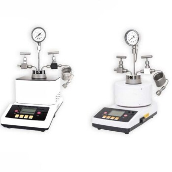
- Customizable Laboratory High Temperature High Pressure Reactors for Diverse Scientific Applications
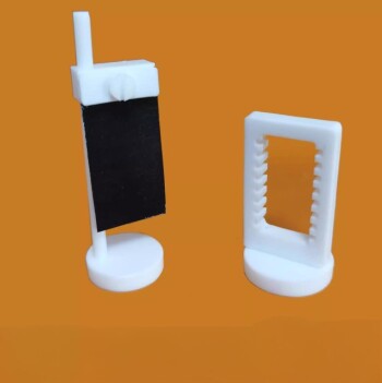
- Custom PTFE Teflon Parts Manufacturer for Hydrothermal Synthesis Reactor Polytetrafluoroethylene Carbon Paper and Carbon Cloth Nano-growth
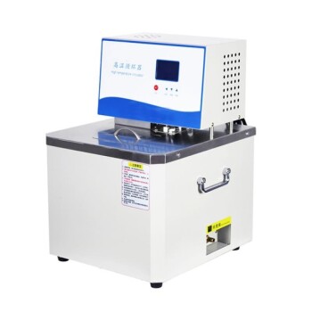
- High Temperature Constant Temperature Heating Circulator Water Bath Chiller Circulator for Reaction Bath
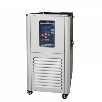
- 10L Chilling Circulator Cooling Water Bath Low Temperature Constant Temperature Reaction Bath
People Also Ask
- How does a CVD tube furnace inhibit the sintering of silver supports? Boost Membrane Durability and Performance
- What is a CVD tube furnace? A Complete Guide to Thin-Film Deposition
- What is the function of a high-temperature CVD tube furnace in 3D graphene foam prep? Master 3D Nanomaterial Growth
- What is the substrate for CVD process? Choosing the Right Foundation for Your Thin Film
- What is the function of a tube furnace in CVD SiC synthesis? Achieving Ultra-Pure Silicon Carbide Powders