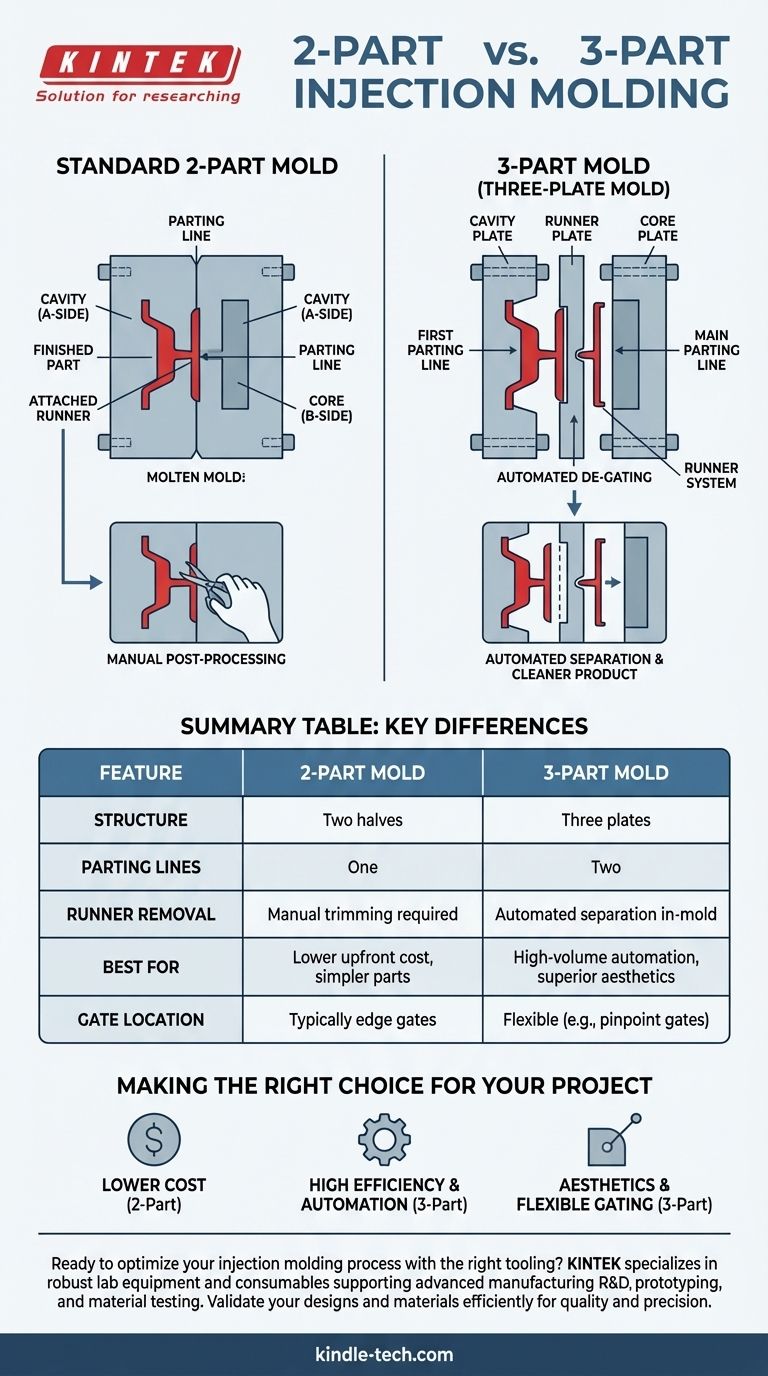
At its core, a 3-part injection mold, often called a three-plate mold, is a more sophisticated tool than a standard 2-part mold. It incorporates an additional floating plate between the main halves of the tool. This design creates two separate parting lines, with the primary function of automatically separating the plastic runner system from the finished part during the mold opening sequence.
The fundamental purpose of a 3-part mold is to achieve manufacturing automation. By mechanically shearing the gate and separating the runner from the part, it eliminates a manual post-processing step, leading to faster cycle times and a cleaner, more consistent final product.
How a Standard 2-Part Mold Sets the Stage
To understand the value of a 3-part mold, it's essential to first recognize the limitations of a standard 2-part design.
The Basic Structure
A conventional mold consists of two halves: the cavity (A-side) and the core (B-side). Molten plastic is injected into the void between them to form the part.
A Single Parting Line
These two halves meet at a single plane called the parting line. When the molding cycle is complete, the mold opens along this line to eject the finished part.
The Attached Runner
In this setup, the runner system—the channels that deliver plastic to the cavity—is molded along with the part and remains attached to it upon ejection. This runner material must then be manually trimmed off in a secondary operation, adding labor cost and time.
The Anatomy of a 3-Part Mold
A 3-part mold introduces a clever mechanical solution to the problem of the attached runner.
The Additional "Runner" Plate
This design adds a third main component, a runner plate (or stripper plate), that sits between the cavity and core plates. This creates a mold with three distinct sections instead of two.
Two Parting Lines
The presence of the third plate creates two parting lines. The mold is designed to open in a specific sequence:
- An initial opening occurs at the first parting line, between the runner plate and the cavity plate. This action pulls the part away from the small gate, effectively shearing or "snapping" the runner off the part.
- A second opening occurs at the main parting line, allowing the now-separated part to be ejected from the mold.
The Automated De-gating Process
This sequenced opening automatically de-gates the part inside the tool. The runner system is ejected separately, completely eliminating the need for manual trimming. This is the central advantage of the design.
Understanding the Trade-offs
While powerful, a 3-part mold is not the default solution. It comes with specific trade-offs that must be considered.
Increased Tool Complexity and Cost
The additional plate, pins, and complex opening mechanism make the mold more difficult to design, manufacture, and assemble. This translates directly to a higher upfront tooling cost compared to a 2-part mold.
Potentially Longer Cycle Times
The two-stage opening sequence adds mechanical movement to the process. In some cases, this can result in a slightly longer overall cycle time than a simple, fast-opening 2-part mold, though this is often offset by the time saved from eliminating manual labor.
Higher Maintenance Requirements
More moving parts mean more surfaces for wear and a greater need for precise alignment. These molds require diligent maintenance to ensure long-term reliability and consistent part quality.
Making the Right Choice for Your Project
Selecting the right mold type depends entirely on your project's specific priorities regarding cost, volume, and quality.
- If your primary focus is minimizing upfront tooling cost: A standard 2-part mold is the more economical choice, assuming the part design allows for an edge gate and you can accommodate a manual de-gating process.
- If your primary focus is high-volume efficiency and automation: A 3-part mold is the superior solution, as it integrates de-gating into the cycle, reducing long-term labor costs and ensuring process consistency.
- If your primary focus is part aesthetics and flexible gate location: A 3-part mold is essential for using pinpoint gates, which can be placed in the center of a part and leave a very small, clean vestige that is cosmetically acceptable.
By understanding the distinct mechanics of each mold type, you can make an informed tooling decision that aligns perfectly with your production goals.
Summary Table:
| Feature | 2-Part Mold | 3-Part Mold |
|---|---|---|
| Structure | Two halves (Cavity & Core) | Three plates (Cavity, Runner, & Core) |
| Parting Lines | One | Two |
| Runner Removal | Manual trimming required | Automated separation in-mold |
| Best For | Lower upfront cost, simpler parts | High-volume automation, superior aesthetics |
| Gate Location | Typically edge gates | Flexible (e.g., pinpoint gates on part face) |
Ready to optimize your injection molding process with the right tooling?
At KINTEK, we specialize in providing robust lab equipment and consumables that support advanced manufacturing R&D, including prototyping and material testing for applications like injection molding. Our solutions help you validate your designs and materials efficiently, ensuring your production—whether it uses a 2-part or 3-part mold—is built on a foundation of quality and precision.
Let's discuss how we can support your laboratory and production needs. Contact our experts today!
Visual Guide
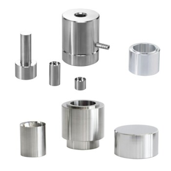
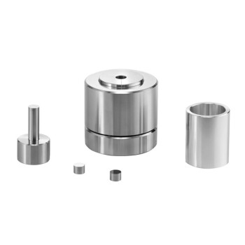
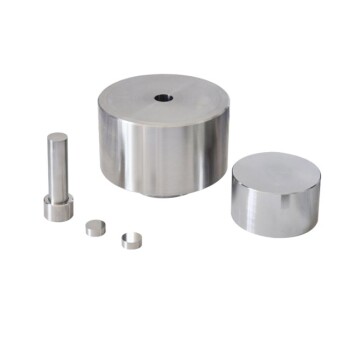
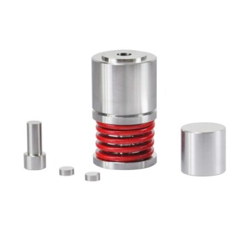
Related Products
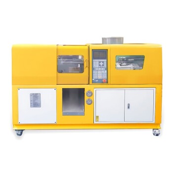
- Small Injection Molding Machine for Lab Use
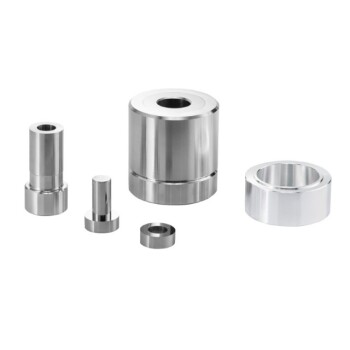
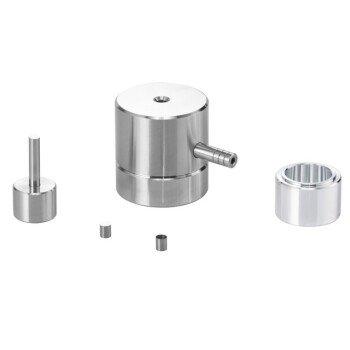
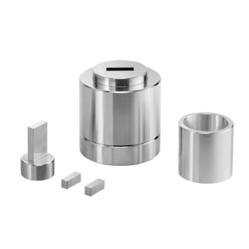
- Ring Press Mold for Lab Applications
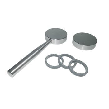
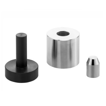
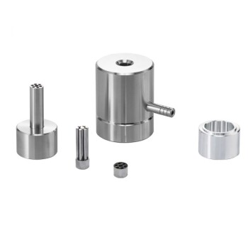
- XRF & KBR plastic ring lab Powder Pellet Pressing Mold for FTIR
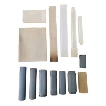
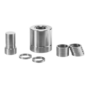
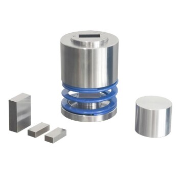
- Isostatic Molding Pressing Molds for Lab
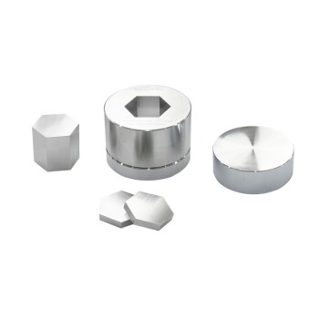
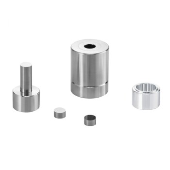
- Cylindrical Press Mold for Lab Applications
People Also Ask
- What is short capacity of injection Moulding machine? Optimize Your Shot Size for Flawless Parts
- What is the importance of injection moulding machine? Unlocking High-Volume, Precision Manufacturing
- What are the 5 steps of injection molding? A Guide to Efficient, High-Quality Production
- What are the advantages and disadvantages of injection molding machine? Maximize Efficiency for Mass Production
- What machine makes molding? Injection Molding Machines for Mass Production