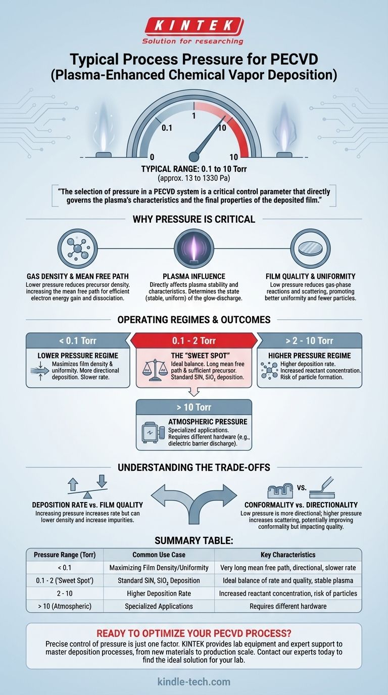
For Plasma-Enhanced Chemical Vapor Deposition (PECVD), the typical process pressure falls within a broad range of 0.1 to 10 Torr (approximately 13 to 1330 Pa). While specific applications can push these boundaries, most common PECVD processes for thin-film deposition operate comfortably within this low-pressure vacuum environment.
The selection of pressure in a PECVD system is not arbitrary; it is a critical control parameter that directly governs the plasma's characteristics and, consequently, the final properties of the deposited film, such as its density, uniformity, and stress.
Why Pressure is a Critical Parameter in PECVD
To understand why this specific pressure range is used, we must look at how it influences the plasma and the deposition reactions. Pressure is one of the primary levers an engineer has to control the outcome of the process.
The Impact on Gas Density and Mean Free Path
At its core, pressure is a measure of the number of gas molecules in the reactor chamber.
Lowering the pressure reduces the density of precursor gas molecules. This increases the mean free path—the average distance an electron can travel before colliding with a gas molecule.
A longer mean free path is crucial. It allows electrons to accelerate and gain significant energy from the applied RF field before a collision, leading to more efficient dissociation of the precursor gases into the reactive species required for film deposition.
The Influence on the Plasma Itself
The pressure directly affects the stability and characteristics of the glow-discharge plasma.
Within the typical range, the plasma can be sustained in a stable, uniform state. If the pressure is too high, the plasma can become unstable, constrict, or lead to arcing. If it's too low, it can become difficult to ignite and sustain the plasma at all.
The Effect on Film Quality and Uniformity
Low pressure is essential for achieving high-quality films. It helps reduce unwanted gas-phase reactions and scattering.
Fewer collisions in the gas phase mean that the reactive species are more likely to travel directly to the substrate surface. This promotes better film uniformity across the wafer and reduces the formation of particles ("dust") within the plasma that can contaminate the film.
The Typical Operating Range and Its Justification
While the full range is quite broad, different regimes within it are used to achieve specific outcomes. The vast majority of processes operate between 50 mTorr and 5 Torr.
The "Sweet Spot": 0.1 to 2 Torr
Many standard PECVD processes, such as depositing silicon nitride (SiN) or silicon dioxide (SiO₂), run in this narrower window.
This range provides an ideal balance. It's low enough to ensure a long mean free path for energetic electrons but high enough to provide a sufficient concentration of precursor molecules for a practical deposition rate.
Lower Pressure Regimes (< 0.1 Torr)
Operating at the lowest end of the pressure range is sometimes done to maximize film density and uniformity.
By minimizing gas-phase scattering, the deposition becomes more directional, which can be beneficial for certain applications. However, this often comes at the cost of a significantly slower deposition rate.
Higher Pressure Regimes (> 5-10 Torr)
Pushing toward higher pressures is less common in standard PECVD. It can lead to a decrease in the mean free path, less efficient plasma generation, and a higher probability of gas-phase particle formation, which degrades film quality.
Specialized techniques like Atmospheric Pressure PECVD exist, but they require entirely different hardware, such as dielectric barrier discharge sources, to operate without the need for a vacuum chamber.
Understanding the Trade-offs
Choosing the right pressure involves balancing competing factors. There is no single "best" pressure; it always depends on the process goals.
Deposition Rate vs. Film Quality
This is the fundamental trade-off. Increasing pressure generally provides more reactant molecules, which can increase the deposition rate. However, this often comes at the expense of film quality, leading to lower density, higher impurities, and poorer uniformity.
Conformality vs. Directionality
At very low pressures, the long mean free path leads to more directional, line-of-sight deposition. This is detrimental when trying to coat complex, three-dimensional structures, a property known as conformality. Increasing pressure increases scattering, which can sometimes improve conformality, but this must be balanced against the negative impacts on film quality.
Process Stability vs. Throughput
Operating at the extreme ends of the pressure spectrum can challenge the stability of the process. Pushing for maximum throughput with high pressure risks plasma arcing and particle generation. Conversely, operating at extremely low pressure can make it difficult to strike and maintain a uniform plasma.
Making the Right Choice for Your Goal
Your choice of process pressure should be dictated by the desired properties of your final film.
- If your primary focus is the highest film quality, density, and uniformity: Operate in the lower end of the spectrum (e.g., 0.1 to 1 Torr) to minimize gas-phase scattering.
- If your primary focus is maximizing throughput and deposition rate: Experiment with the mid-to-upper end of the typical range (e.g., 1 to 5 Torr), but carefully validate that film quality remains within your specifications.
- If your primary focus is coating complex topography (conformality): Pressure is only one factor, but you may need to operate at a slightly higher pressure to induce scattering, in combination with optimizing temperature and gas flow rates.
Ultimately, pressure is a foundational parameter that provides direct control over the plasma environment and the resulting film.
Summary Table:
| Pressure Range (Torr) | Common Use Case | Key Characteristics |
|---|---|---|
| < 0.1 | Maximizing Film Density/Uniformity | Very long mean free path, directional deposition, slower rate |
| 0.1 - 2 ("Sweet Spot") | Standard SiN, SiO₂ Deposition | Ideal balance of rate and quality, stable plasma |
| 2 - 10 | Higher Deposition Rate | Increased reactant concentration, risk of particle formation |
| >10 (Atmospheric) | Specialized Applications | Requires different hardware (e.g., dielectric barrier discharge) |
Ready to Optimize Your PECVD Process?
The precise control of pressure is just one factor in achieving perfect thin films. KINTEK specializes in providing the lab equipment and expert support to help you master your deposition processes. Whether you are developing new materials or scaling up production, our range of PECVD systems and consumables is designed to meet the rigorous demands of modern laboratories.
Let's discuss your specific application needs. Contact our experts today to find the ideal solution for your lab.
Visual Guide
Related Products
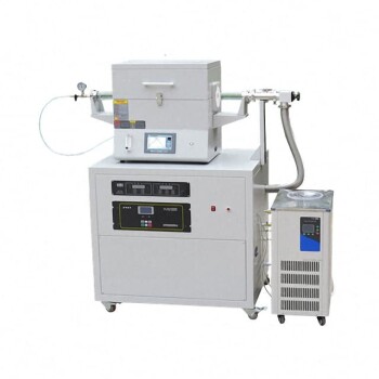
- Chemical Vapor Deposition CVD Equipment System Chamber Slide PECVD Tube Furnace with Liquid Gasifier PECVD Machine
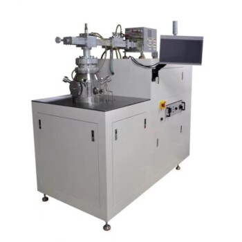
- RF PECVD System Radio Frequency Plasma-Enhanced Chemical Vapor Deposition RF PECVD
- Inclined Rotary Plasma Enhanced Chemical Vapor Deposition PECVD Equipment Tube Furnace Machine
- Inclined Rotary Plasma Enhanced Chemical Vapor Deposition PECVD Equipment Tube Furnace Machine
- 915MHz MPCVD Diamond Machine Microwave Plasma Chemical Vapor Deposition System Reactor
People Also Ask
- How expensive is chemical vapor deposition? Understanding the True Cost of High-Performance Coating
- What is the chemical vapor deposition growth process? Build Superior Thin Films from the Atom Up
- Why is Chemical Vapor Deposition (CVD) equipment uniquely suited for constructing hierarchical superhydrophobic structures?
- How are carbon nanotubes grown? Master Scalable Production with Chemical Vapor Deposition
- What is plasma enhanced chemical vapor deposition PECVD equipment? A Guide to Low-Temperature Thin Film Deposition