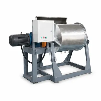
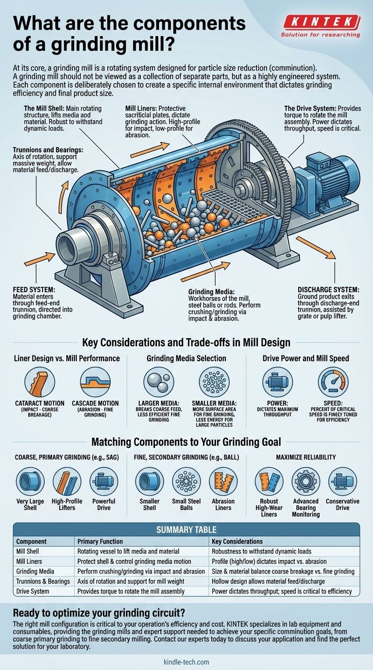
At its core, a grinding mill is a rotating system designed for particle size reduction, known as comminution. Its primary components include the main rotating shell, protective internal liners, the grinding media that performs the work, a support system of trunnions and bearings, and a powerful drive system to rotate the entire assembly.
A grinding mill should not be viewed as a collection of separate parts, but as a highly engineered system. Each component—from the profile of a liner to the size of the grinding media—is deliberately chosen to create a specific internal environment that dictates grinding efficiency and final product size.
The Core Mechanical Components
The primary function of a grinding mill is to convert electrical energy from the drive system into mechanical energy for breaking rock and ore. This conversion happens through the interaction of its core mechanical parts.
The Mill Shell
The mill shell is the large, cylindrical or conical-cylindrical steel body that contains all the other components. It is the main rotating structure of the mill.
Its primary purpose is to provide the rotating vessel that lifts the grinding media and the material being processed. The shell must be incredibly robust to withstand immense dynamic loads.
Mill Liners
Mill liners are sacrificial plates, typically made of high-wear steel alloys or rubber composites, that are bolted to the inside surface of the mill shell.
They serve two critical functions. First, they protect the expensive mill shell from the intense impact and abrasion of the grinding process. Second, their shape (profile) is designed to lift the grinding media and control how it falls, directly influencing the grinding action.
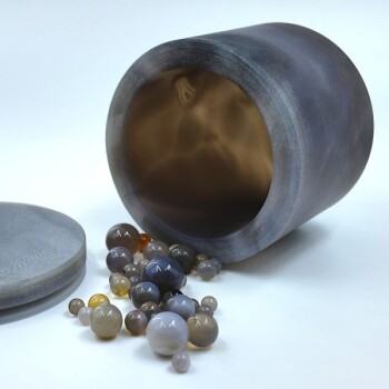
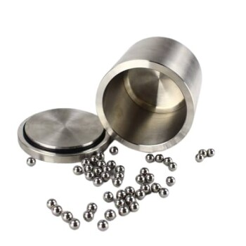
Grinding Media
The grinding media are the workhorses of the mill. These are the loose objects inside the shell that are lifted by rotation and then fall back down, crushing and grinding the material between them.
The most common types are steel balls (in ball mills) or steel rods (in rod mills). In autogenous (AG) or semi-autogenous (SAG) mills, large pieces of the ore itself act as the primary grinding media, sometimes supplemented with a small charge of large steel balls.
Trunnions and Bearings
The trunnions are hollow cylindrical shafts fixed to the center of each end of the mill shell. They act as the axis of rotation for the mill.
These trunnions rest on large, specialized bearings (often hydrostatic or hydrodynamic) that support the massive weight of the mill and its contents while allowing for smooth, low-friction rotation. The hollow design of the trunnions also provides the pathway for material to be fed into and discharged from the mill.
The Drive System
The drive system provides the torque needed to rotate the mill. It must overcome the immense inertia and weight of the shell, liners, media, and ore.
This system typically consists of a large electric motor, a gearbox for speed reduction, and a pinion gear. The pinion engages with a large ring gear (or "girth gear") mounted on the circumference of the mill shell, transferring rotational force. Some modern, large mills use gearless motor drives (GMDs) where the motor is built directly around the mill shell itself.
Understanding the Material Flow System
For a mill to operate continuously, material must be able to enter and exit in a controlled manner. This is managed by the feed and discharge components, which are integral to the trunnions.
The Feed System
Material, often mixed with water to form a slurry, enters the mill through the feed-end trunnion. A feed chute or trunnion liner directs the slurry into the main grinding chamber.
The Discharge System
As new material is fed into the mill, the ground product is displaced and exits through the discharge-end trunnion. A grate or pulp lifter system inside the mill helps separate and guide the correctly sized particles out of the mill for further processing.
Key Considerations and Trade-offs in Mill Design
The selection and design of each component involve significant trade-offs that impact the mill's performance, operating cost, and maintenance schedule.
Liner Design vs. Mill Performance
The profile of the liners is critical. High-profile lifters cause the media to be thrown further into the air before falling, creating high-impact "cataract" motion ideal for breaking large particles. Low-profile lifters cause the media to roll and slide down the shell face, creating an abrasive "cascade" motion ideal for finer grinding.
Grinding Media Selection
The size and material of the grinding media are crucial. Larger media are better at breaking coarse feed but are less efficient for fine grinding. Smaller media provide more surface area and contact points for fine grinding but may not have enough energy to break large particles. The media also wears down over time, representing a major operational cost.
Drive Power and Mill Speed
The power of the drive system determines the maximum load the mill can handle (throughput). The rotational speed, known as the percent of critical speed, is finely tuned. Running too fast will cause the media to be pinned to the shell by centrifugal force, stopping all grinding. Running too slow reduces throughput and efficiency.
Matching Components to Your Grinding Goal
The ideal configuration of a grinding mill is always tied to the specific comminution goal, whether it's liberating minerals from ore or producing a fine powder.
- If your primary focus is coarse, primary grinding (e.g., SAG milling): Your system will feature very large diameter shells, high-profile lifter liners for impact, and a powerful drive system to handle large feed sizes.
- If your primary focus is fine, secondary grinding (e.g., ball milling): Your system will use a smaller diameter shell, a large charge of small-diameter steel balls, and liner profiles that promote abrasion and cascading.
- If your primary focus is maximizing reliability and minimizing downtime: You will invest in robust, high-wear-life liners, advanced bearing monitoring systems, and a conservatively rated drive system.
Understanding how these essential components function as an integrated system is the first step toward optimizing any grinding circuit.
Summary Table:
| Component | Primary Function | Key Considerations |
|---|---|---|
| Mill Shell | Rotating vessel to lift media and material | Robustness to withstand dynamic loads |
| Mill Liners | Protect shell & control grinding media motion | Profile (high/low) dictates impact vs. abrasion |
| Grinding Media | Perform crushing/grinding via impact and abrasion | Size & material balance coarse breakage vs. fine grinding |
| Trunnions & Bearings | Axis of rotation and support for mill weight | Hollow design allows material feed/discharge |
| Drive System | Provides torque to rotate the mill assembly | Power dictates throughput; speed is critical to efficiency |
Ready to optimize your grinding circuit? The right mill configuration is critical to your operation's efficiency and cost. KINTEK specializes in lab equipment and consumables, providing the grinding mills and expert support needed to achieve your specific comminution goals, from coarse primary grinding to fine secondary milling. Contact our experts today to discuss your application and find the perfect solution for your laboratory.
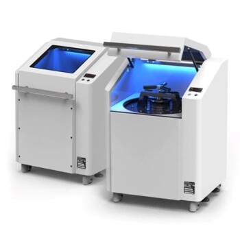
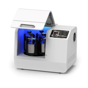
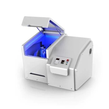
Visual Guide
Related Products
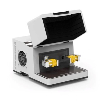
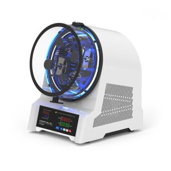
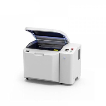
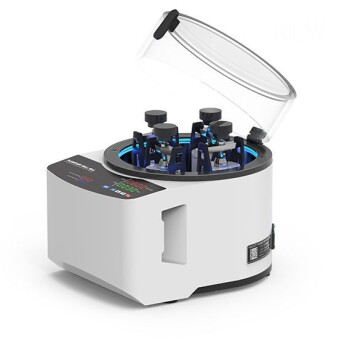
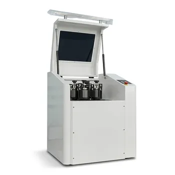
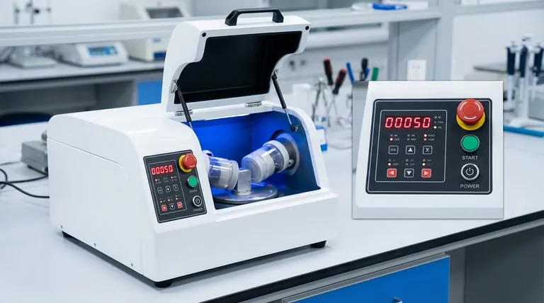
- Laboratory Hybrid Tissue Grinding Mill
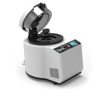
- Laboratory High Throughput Tissue Grinding Mill Grinder
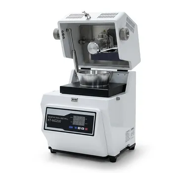
- Laboratory Grinding Mill Mortar Grinder for Sample Preparation
- Vibrating Disc Mill Small Laboratory Grinding Machine
- Laboratory Jar Ball Mill with Alumina Zirconia Grinding Jar and Balls
People Also Ask
- What is the purpose of using a laboratory grinder with specific mesh sieves for oat straw? Optimize Pellet Quality
- What laboratory apparatus is used for grinding? Match the Right Mill to Your Sample Material
- What is the function of laboratory mills? Achieve Precise Particle Size Control for Accurate Analysis
- How do laboratory grinders and standard sieving systems ensure the quality of feedstock for torrefaction?
- What are the different types of laboratory mills? Choose the Right Grinder for Your Sample Material