A battery testing system evaluates Fluorinated Helical Carbon Nanotube (F-HCNT) batteries by executing programmed galvanostatic discharge cycles to measure specific capacity, energy density, and voltage plateaus. These systems are critical for quantifying how the material handles rate performance and cycle stability while capturing unique electrochemical signatures like initial voltage drops and hysteresis phenomena.
The core mission of a battery testing system is to provide a quantitative validation of a material's practical application potential. It bridges the gap between laboratory synthesis and real-world performance by simulating various operational stresses under precise electrical control.
Quantifying Electrochemical Performance Indicators
Discharge Capacity and Energy Density
The system applies precise currents to determine the specific capacity of F-HCNT materials. By integrating the discharge curve, it calculates the energy density, which is a primary metric for evaluating the performance of carbon fluoride-based systems.
Voltage Plateau Stability
For F-HCNT batteries, maintaining a stable voltage plateau is essential for consistent power delivery. Testing systems monitor the voltage throughout the discharge process to ensure the material provides a flat, predictable output rather than a rapid decline.
Rate Performance and Current Density
The system subjects the battery to varying current densities to assess how well the F-HCNT structure handles high-power demands. This "rate capability" test determines if the helical structure effectively facilitates ion transport under aggressive load conditions.
Analyzing Material-Specific Behaviors
Capturing Hysteresis and Initial Voltage Drops
At the start of the discharge cycle, the testing system records voltage drops and hysteresis phenomena. These indicators are vital for understanding the internal resistance and kinetic barriers inherent in the fluorinated carbon structure.
Long-Term Cycle Stability
Industrial-grade systems perform hundreds of charge-discharge cycles to evaluate capacity retention. This identifies how well the F-HCNT material resists degradation and manages volume expansion over the battery's projected lifespan.
Monitoring Real-Time Voltage Windows
Testing systems operate within strictly defined voltage ranges (often between 0.01V and 3.0V) to prevent irreversible material damage. Real-time monitoring allows for the identification of short-circuit signals or irregularities caused by impurities or dendrite growth.
Understanding the Trade-offs
Accuracy vs. Testing Speed
High-precision measurements require lower current densities and longer testing durations. While rapid testing provides quick feedback, it may mask subtle degradation patterns or overlook the full discharge potential of the F-HCNT material.
Data Granularity vs. Storage Complexity
Recording every millisecond of a 200-cycle test generates massive datasets. Engineers must balance the need for high-frequency data capture—essential for identifying short-circuits—with the practicalities of data management and analysis.
Laboratory Conditions vs. Real-World Variables
Battery testing systems typically operate in controlled environments using coin cells. These results may not perfectly translate to large-scale pouch cells where thermal gradients and mechanical stresses become more significant factors in F-HCNT performance.
Applying Testing Insights to Your Objectives
The data gathered by a battery testing system should be used to refine both material synthesis and application engineering.
- If your primary focus is material optimization: Prioritize the analysis of voltage plateaus and initial Coulombic efficiency to determine how fluorination levels impact energy output.
- If your primary focus is power delivery: Focus on rate performance tests at high current densities to verify if the helical structure provides the necessary ion pathways for high-drain applications.
- If your primary focus is commercial longevity: Emphasize long-term cycling tests (200+ cycles) to quantify capacity retention and ensure the material meets industry standards for shelf life and durability.
A robust battery testing protocol is the final gatekeeper that transforms a promising carbon material into a validated energy storage solution.
Summary Table:
| Primary Task | Key Measurement | Impact on F-HCNT Evaluation |
|---|---|---|
| Electrochemical Profiling | Specific Capacity & Energy Density | Quantifies total energy storage potential of carbon fluoride systems. |
| Performance Benchmarking | Voltage Plateau Stability | Ensures consistent power delivery and flat discharge curves. |
| Dynamic Loading | Rate Performance (C-rate) | Evaluates ion transport efficiency within the helical nanotube structure. |
| Durability Testing | Long-Term Cycle Stability | Identifies degradation patterns and capacity retention over time. |
| Kinetic Analysis | Hysteresis & Voltage Drop | Diagnoses internal resistance and kinetic barriers of the material. |
Empower Your Energy Research with KINTEK
Achieving breakthrough performance in F-HCNT and advanced battery materials requires precision at every step. At KINTEK, we provide the specialized laboratory equipment necessary to synthesize and evaluate your next-generation energy solutions.
Our comprehensive portfolio includes:
- Advanced Battery Research Tools: Specialized testers and consumables for accurate data capture.
- High-Temperature Furnaces: CVD, PECVD, vacuum, and atmosphere furnaces for precise material synthesis.
- Preparation Equipment: Hydraulic presses (pellet, hot, isostatic), crushing, and milling systems.
- Reaction Systems: High-temperature high-pressure reactors and autoclaves for advanced chemical processing.
Whether you are a researcher focused on material optimization or an engineer scaling up power delivery, KINTEK offers the reliability and technical support you need.
Ready to elevate your battery testing and material synthesis?
Contact KINTEK Today to Explore Our Solutions
References
- Gaobang Chen, Xian Jian. Helical fluorinated carbon nanotubes/iron(iii) fluoride hybrid with multilevel transportation channels and rich active sites for lithium/fluorinated carbon primary battery. DOI: 10.1515/ntrev-2023-0108
This article is also based on technical information from Kintek Solution Knowledge Base .
Related Products
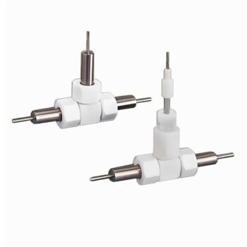
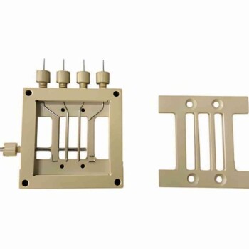
- Customizable Swagelok Type Test Cells for Advanced Battery Research Electrochemical Analysis
- Battery Lab Equipment 304 Stainless Steel Strip Foil 20um Thick for Battery Test
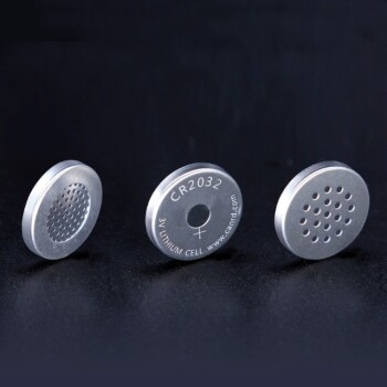
- Button Battery Case for Battery Lab Applications
- Cylindrical Battery Steel Case for Battery Lab
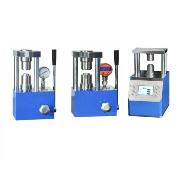
- Laboratory Hydraulic Press Lab Pellet Press for Button Battery
People Also Ask
- What is the difference between a voltaic cell and an electrochemical cell? Understand the Two Types of Energy Conversion
- What is the procedure for starting the experiment and what should be observed? A Step-by-Step Guide for Reliable Electrochemistry
- Why must the electrochemical cell be continuously purged with nitrogen? Ensure Precision in Ni-Cr Corrosion Tests
- Why must electrochemical cells have a condenser and water seal for Alloy 22 studies at 90°C? Ensure Data Integrity
- What is corrosion in an electrochemical cell? Understanding the 4 Components of Metal Decay