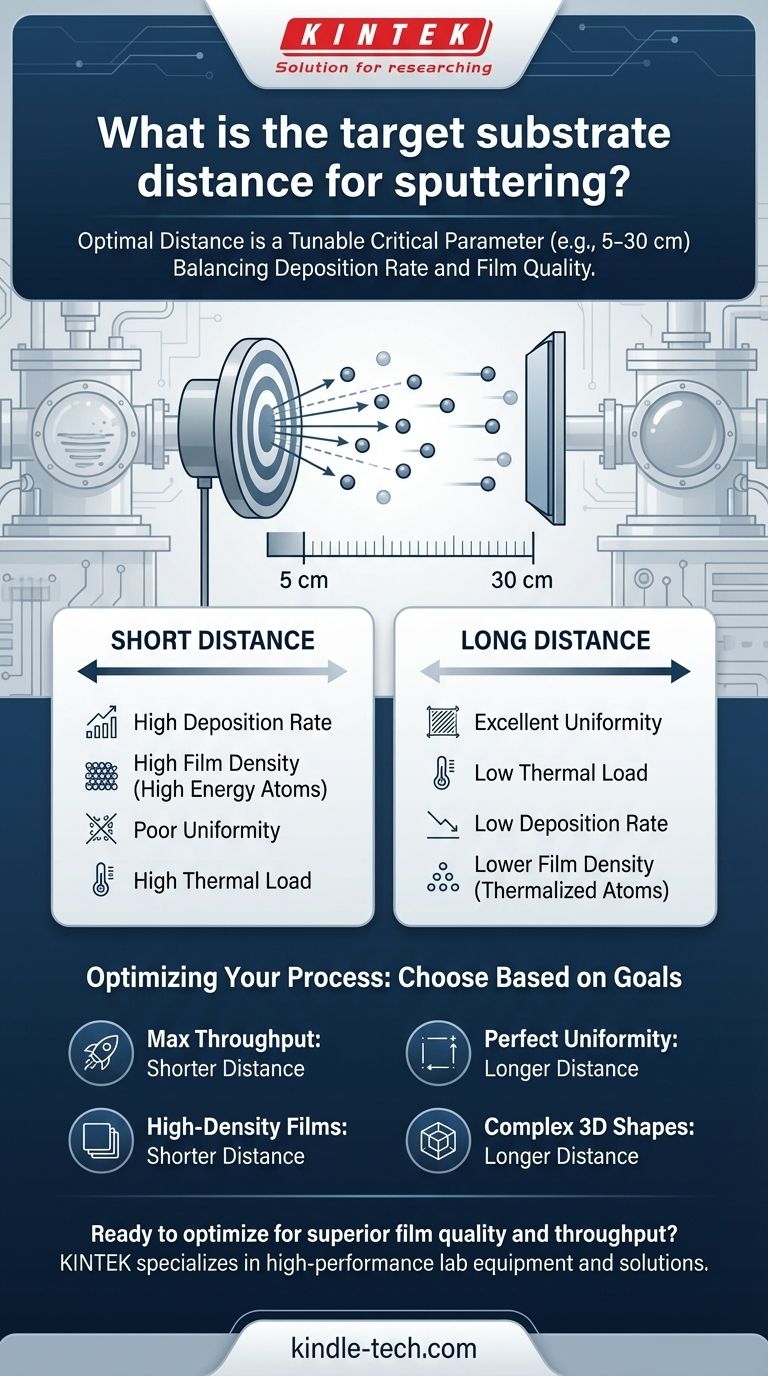
The optimal target-to-substrate distance in sputtering is not a single, universal value. Instead, it is a critical process parameter that must be carefully tuned, typically falling within a range of a few centimeters to several tens of centimeters (e.g., 5-30 cm). The ideal distance is a calculated compromise based on the sputtering system's geometry, the material being deposited, the process pressure, and the desired film properties like uniformity and density.
The core challenge is balancing two competing goals: achieving a high deposition rate and ensuring high film quality. The target-substrate distance is the primary lever you pull to navigate the trade-off between deposition speed and the final film's uniformity, density, and stress.
Why Distance Is a Critical Process Variable
The journey of an atom from the target to the substrate is the defining event in sputtering. The distance of this journey directly influences the energy and trajectory of the depositing atoms, which in turn dictates the final properties of the thin film.
The Role of Pressure and Mean Free Path
The sputtering chamber is not a perfect vacuum; it is filled with a low-pressure process gas, typically Argon. The mean free path is the average distance a sputtered atom can travel before colliding with a gas atom.
This concept is crucial. If the target-substrate distance is much shorter than the mean free path, atoms arrive at the substrate with high energy. If the distance is much longer, they will undergo many collisions, losing energy and changing direction.
Impact on Deposition Rate
A shorter distance means a higher fraction of the sputtered atoms reach the substrate, resulting in a higher deposition rate.
As the distance increases, more atoms are scattered away from the substrate by collisions with gas atoms. This directly lowers the deposition rate.
Impact on Film Uniformity
Sputtered atoms naturally eject from the target in a non-uniform pattern (often described by a cosine distribution).
Increasing the distance allows the atom "cloud" to spread out more before reaching the substrate. This averaging effect significantly improves the thickness uniformity of the film across the substrate's surface, which is critical for large-area coatings.
Impact on Film Energy and Density
At short distances, atoms arrive with higher kinetic energy. This bombardment can produce denser, more compact films.
At longer distances, atoms undergo more collisions and become "thermalized," arriving at the substrate with much lower energy. This can lead to more porous films with lower density.
Understanding the Trade-offs
Choosing the right distance is a matter of prioritizing competing outcomes. There is no single "best" setting, only the best setting for a specific goal.
The Short-Distance Trade-off
A short target-to-substrate distance (e.g., closer to the mean free path) prioritizes speed and energy.
- Benefit: High deposition rate, which is good for production throughput.
- Benefit: High particle energy, leading to denser films.
- Drawback: Poor thickness uniformity, creating a thick spot in the center of the substrate.
- Drawback: The substrate is closer to the plasma and receives more heat, which can damage sensitive materials.
The Long-Distance Trade-off
A long target-to-substrate distance (e.g., several times the mean free path) prioritizes uniformity and control.
- Benefit: Excellent film thickness uniformity over a large area.
- Benefit: Less thermal load on the substrate.
- Drawback: Significantly lower deposition rate, increasing process time and cost.
- Drawback: Lower particle energy can result in less dense films. It also increases the chance of incorporating process gas impurities into the film.
Setting the Optimal Distance for Your Process
Your choice must be guided by the final application of your thin film. The distance should be considered in conjunction with other parameters like gas pressure and sputtering power.
- If your primary focus is maximum throughput: Use a shorter distance, but be prepared to accept compromises on uniformity or use substrate rotation to compensate.
- If your primary focus is perfect film uniformity: Use a longer distance, accepting the slower deposition rate as a necessary cost for quality.
- If your primary focus is high-density films (e.g., for optics or barriers): Favor a shorter distance to preserve particle energy, but carefully manage the process pressure to avoid excessive film stress.
- If your primary focus is coating a complex, 3D shape: A longer distance is often necessary to ensure all surfaces receive some coating material, leveraging gas scattering to your advantage.
Ultimately, mastering the target-substrate distance transforms sputtering from a simple coating technique into a precision engineering tool.
Summary Table:
| Distance Setting | Primary Benefit | Primary Drawback | Best For |
|---|---|---|---|
| Short Distance | High Deposition Rate & High Film Density | Poor Uniformity & High Thermal Load | High-throughput production, dense barrier layers |
| Long Distance | Excellent Uniformity & Low Thermal Load | Low Deposition Rate & Lower Film Density | Large-area coatings, sensitive substrates |
Ready to optimize your sputtering process for superior film quality and throughput?
At KINTEK, we specialize in providing high-performance lab equipment and consumables for all your thin-film deposition needs. Our experts can help you select and configure the right sputtering system to achieve the perfect balance of deposition rate, uniformity, and film density for your specific application.
Contact us today to discuss your requirements and discover how KINTEK's solutions can enhance your laboratory's capabilities and accelerate your research or production.
Visual Guide
Related Products
- Spark Plasma Sintering Furnace SPS Furnace
- Vacuum Induction Melting Spinning System Arc Melting Furnace
- Chemical Vapor Deposition CVD Equipment System Chamber Slide PECVD Tube Furnace with Liquid Gasifier PECVD Machine
- Customer Made Versatile CVD Tube Furnace Chemical Vapor Deposition Chamber System Equipment
People Also Ask
- What is the mechanism of SPS process? A Deep Dive into Rapid, Low-Temperature Sintering
- What are the advantages of CAMI/SPS for W-Cu composite preparation? Reduce cycles from hours to seconds.
- What is SPS sintering method? A Guide to High-Speed, High-Performance Material Fabrication
- What are the fundamentals of spark plasma sintering process? Unlock Rapid, High-Performance Material Consolidation
- What is the process fundamentals of spark plasma sintering? Achieve Rapid, High-Density Material Consolidation


