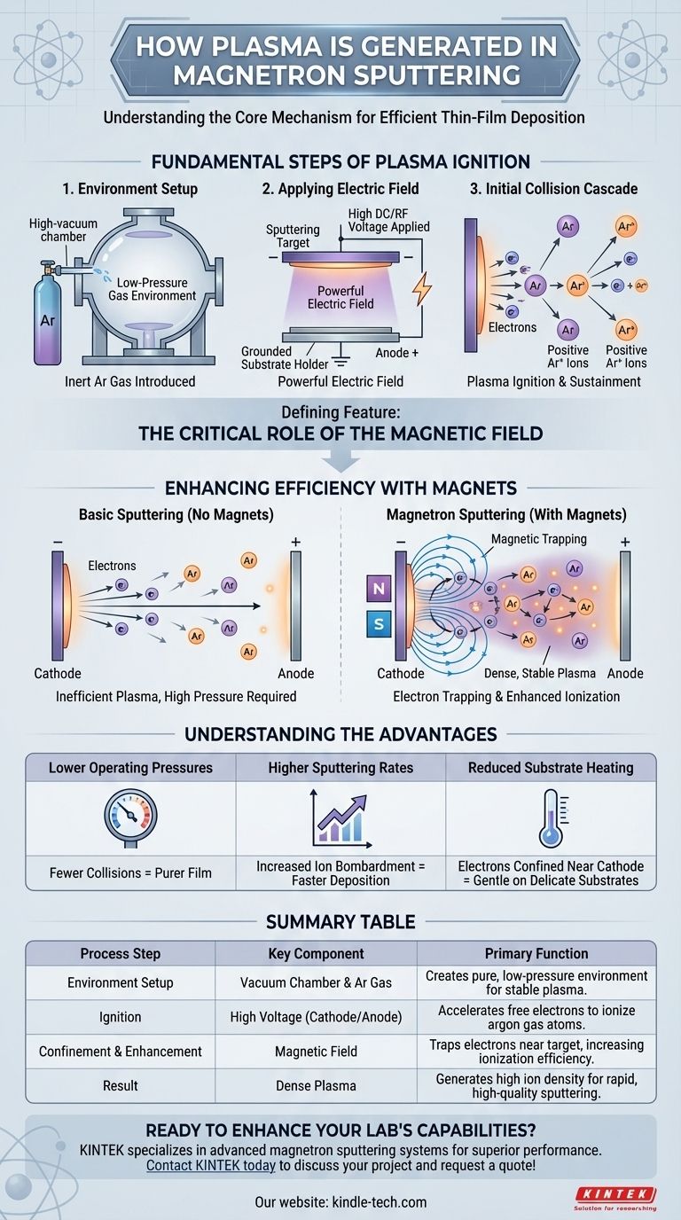
At its core, magnetron sputtering generates plasma by applying a high voltage within a low-pressure gas, creating an electric field that sparks the process. Free electrons accelerate and collide with neutral gas atoms, knocking off more electrons and creating positive ions. This cascade effect ignites and sustains the glowing plasma required to erode the target material.
The defining feature of magnetron sputtering is not just creating a plasma, but efficiently trapping it. By using a magnetic field to confine electrons near the target surface, the process dramatically increases the probability of gas ionization, leading to a denser, more stable plasma that operates at lower pressures and yields much higher deposition rates.
The Fundamental Steps of Plasma Ignition
Establishing the Environment
The entire process occurs inside a high-vacuum chamber. This is crucial for ensuring the purity of the final deposited film.
Once a vacuum is achieved, a small amount of an inert process gas, almost always argon (Ar), is introduced. The pressure is kept very low, creating the ideal conditions for a stable discharge.
Applying the Electric Field
A high DC or RF voltage, often -300V or more, is applied to the sputtering target, which functions as the cathode (negative electrode).
The chamber walls and the substrate holder are typically grounded, acting as the anode (positive electrode). This large voltage difference creates a powerful electric field within the chamber.
The Initial Collision Cascade
There are always a few free electrons present in the gas. The strong electric field violently accelerates these electrons away from the negatively charged cathode.
As these high-energy electrons travel, they collide with neutral argon atoms. If the collision is energetic enough, it knocks an electron off the argon atom, resulting in two free electrons and one positively charged argon ion (Ar+).
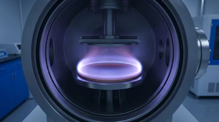
This process repeats in a chain reaction, rapidly creating a dense cloud of free electrons and positive ions. This energized, ionized gas is the plasma. The positive Ar+ ions, being heavy and attracted to the negative target, are then accelerated toward the cathode to begin the sputtering process.
The Critical Role of the Magnetic Field
The Problem with Basic Sputtering
In a simple DC sputtering system without magnets, many of the high-energy electrons make a single trip from the cathode to the anode.
Their path is too short to guarantee a collision with an argon atom. This makes the plasma generation process inefficient, requiring higher gas pressures and resulting in lower sputtering rates.
How Magnets Trap Electrons
In magnetron sputtering, strong magnets are placed behind the target. This creates a magnetic field that is parallel to the target's surface.
This magnetic field forces the light, energetic electrons into a confined, spiraling helical path directly above the target surface. Instead of escaping to the anode, they are trapped in this "racetrack."
The Result: Enhanced Ionization
Because these electrons are trapped, their path length near the cathode increases by orders of magnitude. A single electron can now cause hundreds or thousands of ionization events before its energy is spent.
This dramatically increases the efficiency of plasma generation. It creates a much denser plasma concentrated precisely where it is needed—right in front of the target.
Understanding the Advantages
Lower Operating Pressures
The enhanced ionization efficiency means a stable plasma can be sustained with far less argon gas.
Operating at lower pressure is highly desirable because it means the sputtered atoms have a longer "mean free path." They travel from the target to the substrate with fewer collisions, resulting in a denser and purer deposited film.
Higher Sputtering Rates
A denser plasma contains a much higher concentration of positive argon ions.
This massive increase in ion density leads to a much higher rate of ion bombardment on the target surface. Consequently, atoms are ejected from the target more rapidly, leading to significantly faster film deposition rates.
Reduced Substrate Heating
The magnetic field effectively confines the most energetic electrons near the cathode. This prevents them from bombarding and unnecessarily heating the substrate, which is critical when coating temperature-sensitive materials like plastics.
Making the Right Choice for Your Goal
Understanding this mechanism allows you to control the outcome of your thin-film deposition process.
- If your primary focus is deposition speed: The key is maximizing plasma density by optimizing both the magnetic field strength and the applied power to increase the ion bombardment rate.
- If your primary focus is film purity: The ability to operate at lower pressures, enabled by the magnetic trap, is your greatest advantage as it minimizes the chances of inert gas atoms becoming embedded in your growing film.
- If your primary focus is coating delicate substrates: The electron confinement near the cathode is critical, as it reduces direct electron bombardment and heating of your substrate compared to non-magnetron systems.
Ultimately, the magnetic field transforms sputtering from a brute-force process into a precisely controlled and highly efficient method for engineering materials at the atomic level.
Summary Table:
| Process Step | Key Component | Primary Function |
|---|---|---|
| Environment Setup | Vacuum Chamber & Argon Gas | Creates a pure, low-pressure environment for stable plasma. |
| Ignition | High Voltage (Cathode/Anode) | Accelerates free electrons to ionize argon gas atoms. |
| Confinement & Enhancement | Magnetic Field | Traps electrons near the target, increasing ionization efficiency. |
| Result | Dense Plasma | Generates high ion density for rapid, high-quality sputtering. |
Ready to enhance your lab's thin-film deposition capabilities?
KINTEK specializes in advanced magnetron sputtering systems designed for superior performance. Our equipment delivers the high deposition rates, exceptional film purity, and gentle processing for delicate substrates discussed in this article.
Whether your research demands speed, precision, or material versatility, our solutions are engineered to meet your specific laboratory needs. Let our experts help you select the perfect system to achieve your goals.
Contact KINTEK today to discuss your project and request a quote!
Visual Guide
Related Products
- Microwave Plasma Chemical Vapor Deposition MPCVD Machine System Reactor for Lab and Diamond Growth
- Chemical Vapor Deposition CVD Equipment System Chamber Slide PECVD Tube Furnace with Liquid Gasifier PECVD Machine
- Molybdenum Tungsten Tantalum Special Shape Evaporation Boat
- Hemispherical Bottom Tungsten Molybdenum Evaporation Boat
- Inclined Rotary Plasma Enhanced Chemical Vapor Deposition PECVD Equipment Tube Furnace Machine
People Also Ask
- What pressure is needed for chemical vapor deposition of diamonds? Master the Low-Pressure 'Sweet Spot'
- How is a diamond formed from CVD? The Science of Growing Diamonds Atom by Atom
- How does MPCVD work? A Guide to Low-Temperature, High-Quality Film Deposition
- How are CVD diamonds created? Discover the Science of Lab-Grown Diamond Precision
- What are the advantages of a Microwave Plasma CVD reactor for MCD/NCD coatings? Precision Multilayer Diamond Engineering