There is no single universal value for an acceptable pressure drop across a filter. Instead, this critical metric is defined by the filter's manufacturer and the specific operational requirements of your system. It is a dynamic indicator of filter health, not a static number.
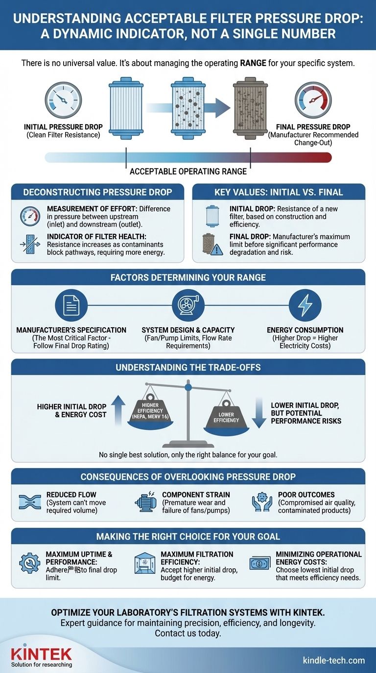
The core takeaway is to reframe the question. Rather than seeking a single "acceptable" pressure drop, the goal is to understand the operating range—from the initial clean-filter pressure drop to the final recommended change-out pressure drop—as specified by the manufacturer for your system.
Deconstructing Pressure Drop: An Indicator of System Health
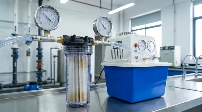
Pressure drop is the measurement of the resistance a fluid (like air or a liquid) encounters as it passes through a filter. This resistance is fundamental to how a filter works.
What Pressure Drop Actually Measures
Think of pressure drop as a measurement of effort. It is the difference in pressure between the upstream (inlet) side of the filter and the downstream (outlet) side.
A brand-new, clean filter presents a certain amount of resistance by design. As that filter captures contaminants, the pathways for the fluid to pass through become progressively blocked, requiring more energy to push the fluid through. This increased resistance is what we see as a rise in pressure drop.
The Two Key Values: Initial vs. Final
To manage any filtration system, you must know two numbers, not one:
- Initial Pressure Drop: This is the resistance of a clean, brand-new filter. This value is determined by the filter's construction and its efficiency rating.
- Final Pressure Drop: This is the manufacturer-recommended maximum pressure drop at which the filter should be replaced. Operating beyond this point leads to significant performance degradation and risks system damage.
Why a Higher Initial Drop Isn't Always Bad
A common misconception is that a low initial pressure drop is always better. However, as the references note, there is a direct relationship between filtration efficiency and pressure drop.
High-efficiency filters (like HEPA or MERV 16) have very dense media to capture tiny particles. This dense structure inherently creates more resistance, leading to a higher initial pressure drop compared to a less-efficient filter. This is a design feature, not a flaw.
Factors That Determine Your "Acceptable" Range
The correct pressure drop range for your application is not arbitrary. It is a calculated value based on several interconnected factors.
The Manufacturer's Specification
This is the most critical factor. The filter manufacturer has tested the filter's structural integrity and performance curve. They provide the final pressure drop recommendation to ensure the filter operates effectively without collapsing or failing. Always use the manufacturer's specified final pressure drop as your primary guide.
System Design and Fan/Pump Capacity
Your system's fan or pump is designed to operate against a certain amount of total resistance. As the filter loads and pressure drop increases, the fan or pump must work harder to maintain the desired flow rate.
If the pressure drop becomes too high, the fan's capacity may be exceeded, leading to a significant drop in fluid flow. This can starve the system, reduce heating or cooling capacity, or compromise a critical industrial process.
Energy Consumption
Pushing air or liquid through a higher resistance requires more energy. Therefore, a higher pressure drop directly translates to higher electricity costs for running the system's fan or pump. The "acceptable" range is often a balance between filtration goals and energy budget.
Understanding the Trade-offs
Choosing and managing filters based on pressure drop involves balancing competing priorities. There is no single "best" solution, only the best solution for your specific goal.
Efficiency vs. Energy Cost
This is the primary trade-off. To achieve higher filtration efficiency, you must accept a higher initial pressure drop and, consequently, a higher baseline energy cost. Forcing a system to use a filter it wasn't designed for can dramatically increase operating expenses.
Filter Lifespan vs. Replacement Cost
A filter with a very large surface area may have a lower initial pressure drop and take longer to reach its final pressure drop, giving it a longer service life. However, this filter may be more expensive upfront. Deciding what is "acceptable" involves calculating the total cost of ownership, including materials, labor for replacement, and energy.
The Cost of Inaction: Overlooking Pressure Drop
Ignoring a high pressure drop reading has clear consequences. These can include:
- Reduced Flow: The system can no longer move the required volume of air or fluid.
- Component Strain: Fans and pump motors work harder, leading to premature wear and potential failure.
- Poor Outcomes: In an HVAC system, this means poor air quality and comfort. In an industrial process, it can mean a contaminated final product.
Making the Right Choice for Your Goal
Your definition of "acceptable" pressure drop depends entirely on your operational priority. Monitor the pressure differential and use the manufacturer's final pressure drop rating as your signal to act.
- If your primary focus is maximum system uptime and performance: Adhere strictly to the manufacturer's final pressure drop limit to prevent flow reduction and component strain.
- If your primary focus is maximum filtration efficiency (e.g., cleanrooms, healthcare): Select the high-efficiency filter your system requires, accept the higher initial pressure drop, and budget for the corresponding energy costs.
- If your primary focus is minimizing operational energy costs: Choose the filter with the lowest initial pressure drop that still meets your minimum efficiency requirements, and ensure your system was designed for it.
By treating pressure drop as a dynamic guide for maintenance rather than a static rule, you gain precise control over your system's health, efficiency, and cost.
Summary Table:
| Key Concept | Description |
|---|---|
| Initial Pressure Drop | The resistance of a clean, new filter. A baseline set by the filter's design and efficiency. |
| Final Pressure Drop | The manufacturer-recommended maximum resistance before the filter should be replaced. |
| Primary Goal | Monitor the pressure drop from initial to final to maintain system health and performance. |
| Key Trade-off | Higher filtration efficiency typically means a higher initial pressure drop and energy cost. |
Optimize your laboratory's filtration systems with KINTEK.
Managing filter pressure drop is critical for maintaining the precision, efficiency, and longevity of your lab equipment. Whether you're running HVAC systems for a controlled environment or specialized filtration for sensitive processes, the right consumables and expert guidance are essential.
KINTEK specializes in providing high-quality lab equipment and consumables, including filters designed for optimal performance and energy efficiency. We can help you select the right products to balance your specific needs for purity, system uptime, and operational cost.
Let our experts help you achieve peak performance. Contact KINTEK today to discuss your laboratory's filtration needs and ensure your systems operate within their ideal pressure drop range.
Visual Guide
Related Products
- Circulating Water Vacuum Pump for Laboratory and Industrial Use
- Oil Free Diaphragm Vacuum Pump for Laboratory and Industrial Use
- Longpass Highpass Filters for Optical Applications
- Laboratory Rotary Vane Vacuum Pump for Lab Use
- Variable Speed Peristaltic Pump
People Also Ask
- What is the purpose of the compression chamber in a vacuum pump? The Heart of Vacuum Generation
- What determines the vacuum degree achievable by a water circulating vacuum pump? Unlock the Physics of Its Limits
- Why is a water circulating vacuum pump suitable for handling flammable or explosive gases? Inherent Safety Through Isothermal Compression
- What is the primary function of a vacuum pump? Remove Gas Molecules to Create a Controlled Vacuum
- What can I use a vacuum pump for? Powering Industrial Processes from Packaging to Automation
