At its core, the theory of RF sputtering describes a physical vapor deposition method that uses a radio frequency (RF) power source to eject atoms from a target material, which then deposit as a thin film onto a substrate. Unlike simpler DC sputtering methods, the alternating RF field is specifically designed to overcome the primary challenge of sputtering insulating (dielectric) materials by preventing a process-halting buildup of electrical charge on the target surface.
The central principle of RF sputtering is the use of an alternating electric field. This field not only creates the plasma needed for sputtering but, more critically, it periodically floods the target with electrons to neutralize the positive ion charge that would otherwise accumulate on insulating materials, allowing for continuous and stable deposition.
The Foundation: How Sputtering Works
Creating a Plasma Environment
The entire sputtering process takes place within a vacuum chamber filled with a small amount of an inert gas, most commonly Argon (Ar).
A high voltage is applied between two electrodes: the cathode (the target material to be deposited) and the anode (where the substrate is placed). This voltage ignites the inert gas, stripping electrons from the gas atoms and creating a plasma—a glowing, ionized gas containing positive ions and free electrons.
The Mechanism of Ion Bombardment
The positively charged gas ions (e.g., Ar+) are accelerated by the electric field and powerfully collide with the negatively charged target.
This collision transfers momentum, dislodging or "sputtering" atoms from the target material. These sputtered atoms travel through the chamber and land on the substrate, gradually building up a thin, uniform film.
Why Radio Frequency is the Critical Component
The Insulator Problem: Charge Buildup
In standard DC sputtering, the target is held at a constant negative voltage. This works perfectly for conductive metal targets, as they can easily dissipate the positive charge from the impacting ions.
However, if the target is an insulating material (like a ceramic or oxide), the positive charge from the arriving ions accumulates on its surface. This buildup eventually repels new incoming positive ions, effectively extinguishing the plasma and stopping the sputtering process.
The RF Solution: An Alternating Field
RF sputtering solves this by using an alternating current power source, typically fixed at an industry-standard 13.56 MHz. The rapidly flipping voltage creates two distinct half-cycles.
During the negative half-cycle, the target is bombarded by positive ions, causing sputtering just like in the DC process.
During the brief positive half-cycle, the target attracts a shower of highly mobile electrons from the plasma. These electrons instantly neutralize the positive charge that accumulated during the negative cycle, "resetting" the target surface and allowing the process to continue.
Developing a Negative Self-Bias
A crucial component in an RF system is a blocking capacitor, placed between the power supply and the target. Because electrons are much more mobile than the heavier ions, the target collects more electrons during the positive cycle than it does ions during the negative cycle.
This imbalance forces the target to develop an overall negative DC bias, ensuring it consistently attracts the positive ions needed for sputtering, even as the voltage alternates.
Understanding the Trade-offs of RF Sputtering
Slower Deposition Rates
The primary drawback of RF sputtering is its slower deposition rate compared to DC sputtering. A portion of each cycle is dedicated to neutralizing charge rather than actively sputtering material, which reduces overall efficiency.
Increased System Complexity and Cost
RF power supplies and the required impedance-matching networks (which ensure efficient power transfer to the plasma) are significantly more complex and expensive than their DC counterparts.
Material and Substrate Considerations
While it is the go-to method for dielectrics, RF sputtering is less cost-effective for depositing thick conductive films where DC methods excel. The higher cost can also make it a less economical choice for coating very large substrates.
Making the Right Choice for Your Goal
The decision between RF and other sputtering methods is almost entirely driven by the electrical properties of your target material.
- If your primary focus is depositing conductive materials (metals): DC sputtering is typically the faster, simpler, and more cost-effective choice.
- If your primary focus is depositing insulating materials (ceramics, oxides): RF sputtering is the necessary and standard industry method to prevent charge buildup.
- If your primary focus is research or process versatility: An RF sputtering system is the most flexible option, as it is capable of depositing both insulating and conductive materials.
By enabling the deposition of a vast range of non-conductive materials, RF sputtering is the foundational technology behind countless modern electronic and optical components.
Summary Table:
| Key Aspect | Description |
|---|---|
| Core Principle | Uses a radio frequency (RF) alternating field to prevent charge buildup on insulating targets. |
| Standard Frequency | 13.56 MHz |
| Primary Application | Deposition of dielectric/insulating materials (e.g., ceramics, oxides). |
| Key Advantage | Enables sputtering of materials that would halt a DC sputtering process. |
| Main Trade-off | Slower deposition rates compared to DC sputtering. |
Ready to deposit high-quality thin films from insulating materials?
KINTEK specializes in advanced lab equipment, including RF sputtering systems designed for precise and reliable deposition of ceramics, oxides, and other dielectrics. Our solutions help researchers and engineers overcome material challenges and achieve superior results.
Contact our experts today to discuss how an RF sputtering system can advance your laboratory's capabilities!
Visual Guide

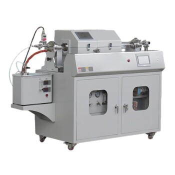
Related Products
- RF PECVD System Radio Frequency Plasma-Enhanced Chemical Vapor Deposition RF PECVD
- Chemical Vapor Deposition CVD Equipment System Chamber Slide PECVD Tube Furnace with Liquid Gasifier PECVD Machine
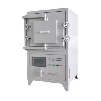
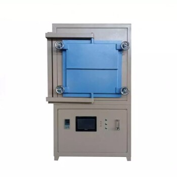
- 1200℃ Controlled Atmosphere Furnace Nitrogen Inert Atmosphere Furnace
- 1400℃ Controlled Atmosphere Furnace with Nitrogen and Inert Atmosphere
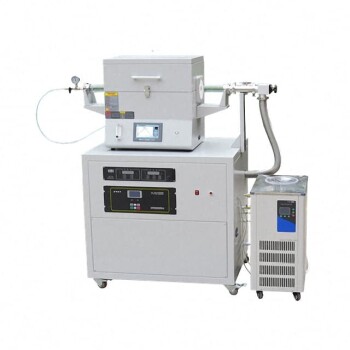
- Split Chamber CVD Tube Furnace with Vacuum Station Chemical Vapor Deposition System Equipment Machine
People Also Ask
- What are the benefits of PECVD? Achieve Superior Low-Temperature Thin Film Deposition
- How are PECVD and CVD different? A Guide to Choosing the Right Thin-Film Deposition Process
- What are the applications of PECVD? Essential for Semiconductors, MEMS, and Solar Cells
- Why is PECVD environment friendly? Understanding the Eco-Friendly Benefits of Plasma-Enhanced Coating
- How does RF power create plasma? Achieve Stable, High-Density Plasma for Your Applications