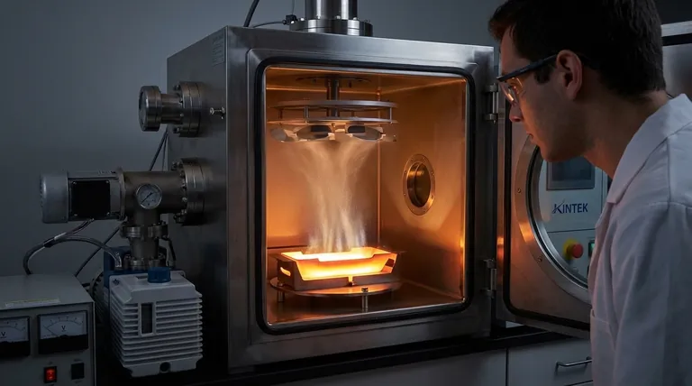
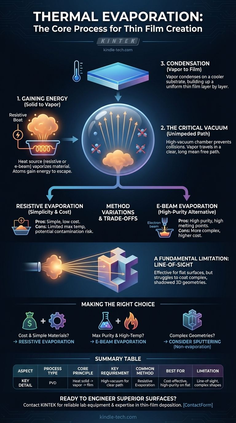
In essence, thermal evaporation is a physical vapor deposition (PVD) method that uses intense heat to turn a solid material into a gas inside a vacuum. This vapor then travels and condenses onto a cooler surface, known as a substrate, to form an extremely thin and uniform film. It is one of the most fundamental techniques for creating high-performance coatings at the nanoscale.
The core challenge in many advanced technologies is applying a perfectly uniform, ultra-thin layer of one material onto another. Thermal evaporation solves this by using heat to "boil" a source material in a vacuum, allowing its atoms to travel unimpeded and re-solidify as a pristine film on a target surface.
The Core Principle: From Solid to Vapor to Film
The entire process is governed by a straightforward sequence of physical state changes, precisely controlled within a specialized environment.
Gaining Energy to Escape
At its heart, evaporation occurs when the atoms of a material gain enough thermal energy to overcome the forces binding them together in a solid or liquid state. In thermal evaporation, this energy is deliberately supplied by a heat source.
As the source material heats up, its vapor pressure increases until it begins to sublimate or evaporate, releasing a cloud of individual atoms or molecules.
The Critical Role of the Vacuum
This process must occur in a high-vacuum chamber. The vacuum is not a trivial detail; it is essential for success.
By removing most of the air and other gas molecules, the vacuum creates a clear path for the vaporized material to travel. This long "mean free path" prevents the coating atoms from colliding with air particles, which would otherwise scatter them and introduce impurities into the final film.
Condensation on the Substrate
The vaporized atoms travel in a straight, line-of-sight path from the source to the cooler substrate positioned above or near it. Upon contact with the cooler surface, the atoms rapidly lose their energy and condense back into a solid state.
This controlled condensation builds up, layer by layer, to form a thin, solid, and highly pure film on the substrate's surface.
Anatomy of a Resistive Evaporation System
The most common form of thermal evaporation is resistive thermal evaporation. It is named for the way it generates heat through electrical resistance.
The Heat Source: The Resistive Boat
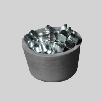
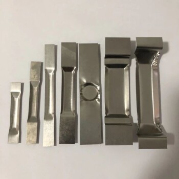
The heating element is typically a small container made from a refractory metal like tungsten, often shaped like a "boat" with a dimple or a basket-like coil. The material to be evaporated is placed inside this boat.
A high electrical current is passed through the boat. Due to its electrical resistance, the boat heats up rapidly—often to thousands of degrees—transferring that thermal energy directly to the source material.
The Source Material: The Coating Foundation
This is the solid—often in pellet or wire form—that you intend to deposit as a thin film. The choice of material depends entirely on the desired properties of the final coating, such as electrical conductivity, optical reflectivity, or hardness.
The Substrate: The Deposition Target
The substrate is the object or material being coated. This could be a silicon wafer for a microchip, a glass lens for an anti-reflective coating, or a medical implant. It is strategically placed to intercept the flow of vapor from the source.
Understanding the Trade-offs and Variations
While effective, resistive thermal evaporation is not the only method, and it comes with specific limitations. Understanding these is key to making the right process decision.
Resistive Evaporation: Simplicity and Cost
The primary advantage of resistive evaporation is its simplicity and relatively low cost. The equipment is less complex than other PVD methods, making it accessible for a wide range of research and production applications.
However, its main drawback is that it is not suitable for materials with very high evaporation temperatures. There is also a small risk of the boat material itself evaporating slightly and contaminating the film.
E-Beam Evaporation: A High-Purity Alternative
For more demanding applications, e-beam (electron beam) evaporation is used. In this process, a high-energy beam of electrons is fired at the source material, generating intense, localized heat.
This method can evaporate materials with extremely high melting points and produces films of exceptional purity, as the heat source (the electron beam) makes no physical contact with the material.
The Line-of-Sight Limitation
A fundamental constraint of all thermal evaporation methods is that they are line-of-sight processes. The vapor travels in a straight line from the source to the substrate.
This means it is excellent for coating flat surfaces but struggles to uniformly coat complex, three-dimensional shapes with undercuts or hidden surfaces.
Making the Right Choice for Your Goal
Selecting the correct deposition technique depends on your specific goals for purity, material choice, and component geometry.
- If your primary focus is cost-effective coating for simpler materials: Standard resistive thermal evaporation is the most direct and economical choice.
- If your primary focus is achieving maximum purity or coating high-temperature materials: E-beam evaporation offers superior performance and cleanliness.
- If your primary focus is coating complex 3D geometries uniformly: You should investigate non-evaporation techniques like sputtering, which do not have the same line-of-sight limitations.
By understanding these fundamental principles, you can deliberately engineer material surfaces and create components with precisely tailored properties.
Summary Table:
| Aspect | Key Detail |
|---|---|
| Process Type | Physical Vapor Deposition (PVD) |
| Core Principle | Heating a solid source material to create a vapor that condenses on a substrate |
| Key Requirement | High-vacuum environment for a clear, unimpeded path |
| Common Method | Resistive Evaporation (using a heated metal boat) |
| Best For | Cost-effective, high-purity coatings on flat surfaces |
| Limitation | Line-of-sight process; struggles with complex 3D shapes |
Ready to Engineer Superior Surfaces?
Choosing the right deposition technique is critical for your project's success. Whether you need the cost-effectiveness of resistive evaporation or the high-purity capabilities of e-beam systems, KINTEK has the expertise and equipment to meet your laboratory's specific needs.
We specialize in providing reliable lab equipment and consumables for thin-film deposition, helping you create components with precisely tailored properties.
Contact our experts today to discuss your application and find the perfect thermal evaporation solution for your lab.
Visual Guide
Related Products
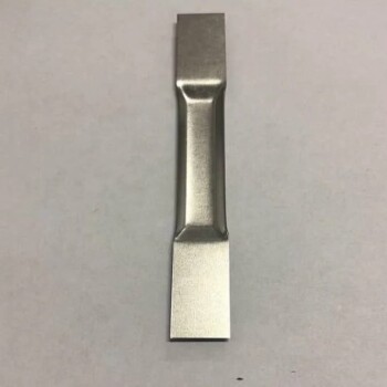
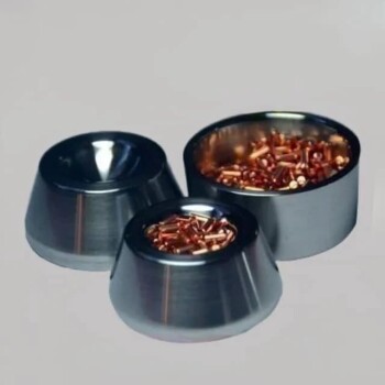
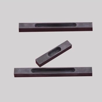
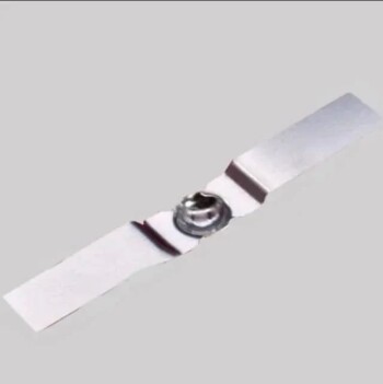
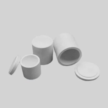
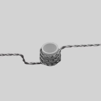
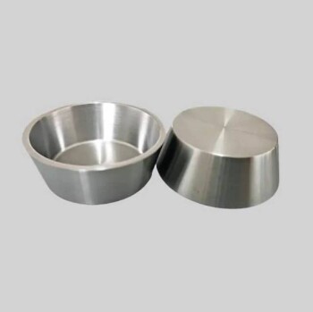
- Molybdenum Tungsten Tantalum Evaporation Boat for High Temperature Applications
- Aluminized Ceramic Evaporation Boat for Thin Film Deposition
- Evaporation Boat for Organic Matter
- Chemical Vapor Deposition CVD Equipment System Chamber Slide PECVD Tube Furnace with Liquid Gasifier PECVD Machine
- Multi Heating Zones CVD Tube Furnace Machine Chemical Vapor Deposition Chamber System Equipment
People Also Ask
- How does a molybdenum evaporation source function in H2S for MoS2 synthesis? Master Reactive Film Deposition
- What is the thermal evaporation method in thin film? A Guide to Simple, Cost-Effective PVD
- What is the source of evaporation for thin film? Choosing Between Thermal and E-Beam Methods
- How source material is evaporated during deposition? A Guide to Resistive vs. E-Beam Methods
- What are the sources of thermal evaporation? A Guide to Resistive vs. E-Beam Heating