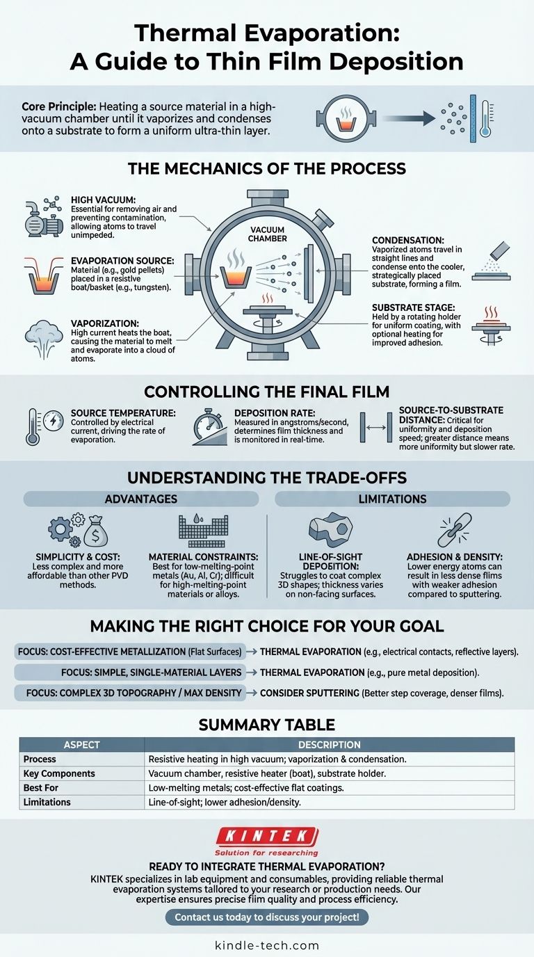
At its core, thermal evaporation is a straightforward method for creating an ultra-thin layer of material on a surface. This technique, also known as resistive evaporation, involves heating a source material inside a high-vacuum chamber until it vaporizes. These vaporized atoms then travel through the vacuum and condense onto a cooler target surface, known as a substrate, forming a uniform thin film.
The critical takeaway is that thermal evaporation is a line-of-sight deposition process governed by a simple principle: you heat a material in a vacuum until it becomes a gas, which then solidifies onto a target. Success hinges on precisely controlling temperature, vacuum level, and geometry to achieve the desired film characteristics.
The Mechanics of the Process
To truly understand thermal evaporation, we must break down its core components and sequence. The entire process takes place within a sealed vacuum chamber to ensure the purity and quality of the final film.
The Critical Role of the Vacuum
The process must occur in a high vacuum for two primary reasons. First, it removes air molecules that would otherwise collide with the vaporized material atoms, scattering them and preventing them from reaching the substrate.
Second, a vacuum eliminates unwanted chemical reactions, such as oxidation, that would contaminate the film and alter its properties.
The Evaporation Source
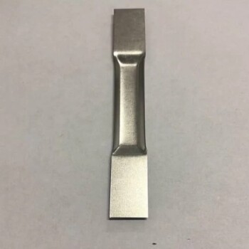
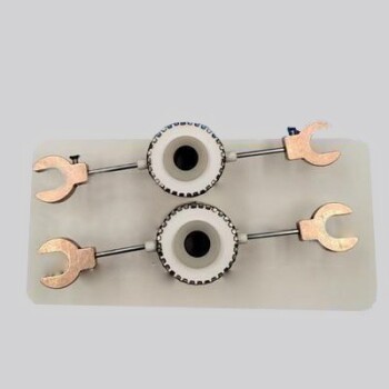
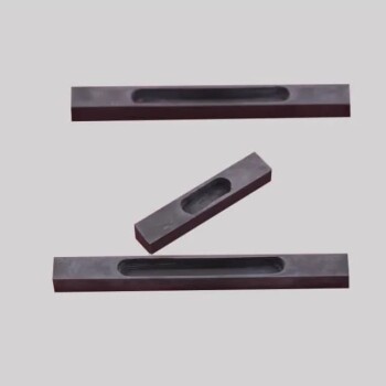
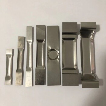
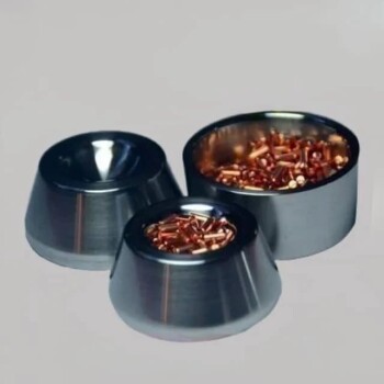
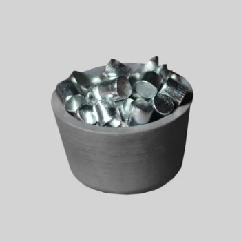
The source material, often in the form of pellets or wire, is placed in a container commonly called a "boat" or "basket." This boat is made from a material with a very high melting point, such as tungsten or molybdenum.
This container acts as a resistive heater. A high electrical current is passed through it, causing it to glow and heat up intensely, transferring that thermal energy to the source material.
From Solid to Vapor to Film
As the current increases, the boat's temperature rises dramatically, causing the source material to first melt and then evaporate, releasing a cloud of atoms or molecules.
These vaporized particles travel in straight lines away from the source. When they strike the cooler substrate—which is strategically placed above the source—they rapidly cool and condense, building up layer by layer to form a solid thin film.
The Substrate Stage
The substrate is held in place by a specialized holder. This holder can often be rotated to ensure the vapor coats the substrate evenly across its entire surface.
In some applications, the substrate holder is also heated. This gives the condensing atoms more surface energy, which can improve the film's adhesion and crystalline structure.
Controlling the Final Film
The final thickness and quality of the deposited film are not left to chance. They are controlled by manipulating several key process variables.
Source Temperature
The temperature of the evaporation source, controlled by the electrical current, is the primary driver of the process. A higher temperature leads to a higher rate of evaporation, which in turn increases the deposition rate on the substrate.
Deposition Rate
The deposition rate—measured in angstroms or nanometers per second—determines how quickly the film grows. This is monitored in real-time to achieve a precise final thickness, from a few nanometers to several microns.
Source-to-Substrate Distance
The physical distance between the evaporation source and the substrate is critical. A greater distance can lead to a more uniform film but will also decrease the deposition rate, as the vapor cloud expands over a larger area.
Understanding the Trade-offs
Like any technical process, thermal evaporation has distinct advantages and limitations that make it suitable for some applications but not others.
Advantage: Simplicity and Cost
Thermal evaporation systems are generally less complex and more affordable than other physical vapor deposition (PVD) methods like sputtering or electron-beam evaporation. This makes it an accessible technique for many applications.
Limitation: Material Constraints
The process is best suited for materials with relatively low evaporation temperatures, such as gold, aluminum, or chromium. Materials with extremely high melting points are difficult to evaporate and can damage the source boat itself. It is also unsuitable for alloys whose components have vastly different evaporation rates.
Limitation: Line-of-Sight Deposition
Because the vapor travels in straight lines, thermal evaporation struggles to coat complex, three-dimensional shapes with undercuts or trenches. The surfaces directly facing the source receive the thickest coating, while vertical sidewalls receive very little.
Limitation: Adhesion and Density
The energy of the atoms arriving at the substrate is relatively low (purely thermal). This can sometimes result in films with lower density and weaker adhesion compared to higher-energy processes like sputtering, though substrate heating can help mitigate this.
Making the Right Choice for Your Goal
Selecting the right deposition technique requires understanding its capabilities in the context of your final objective.
- If your primary focus is cost-effective metallization on flat surfaces: Thermal evaporation is an excellent choice for applications like creating electrical contacts in solar cells or reflective layers on glass.
- If your primary focus is creating simple, single-material layers: The straightforward nature of the process makes it ideal for depositing pure metals where film purity is important but not paramount.
- If your primary focus is coating complex 3D topography or achieving maximum film density: You should evaluate alternative methods like sputtering, which provides better "step coverage" and produces more energetic, denser films.
Ultimately, understanding these fundamental principles and limitations is the key to effectively leveraging thermal evaporation for your specific application.
Summary Table:
| Aspect | Description |
|---|---|
| Process | Resistive heating of a source material in a high-vacuum chamber, causing vaporization and condensation on a substrate. |
| Key Components | Vacuum chamber, resistive heater (boat/basket), substrate holder. |
| Best For | Low-melting-point metals (e.g., gold, aluminum); cost-effective coating of flat surfaces. |
| Limitations | Line-of-sight deposition (poor for 3D shapes); lower adhesion/density vs. sputtering. |
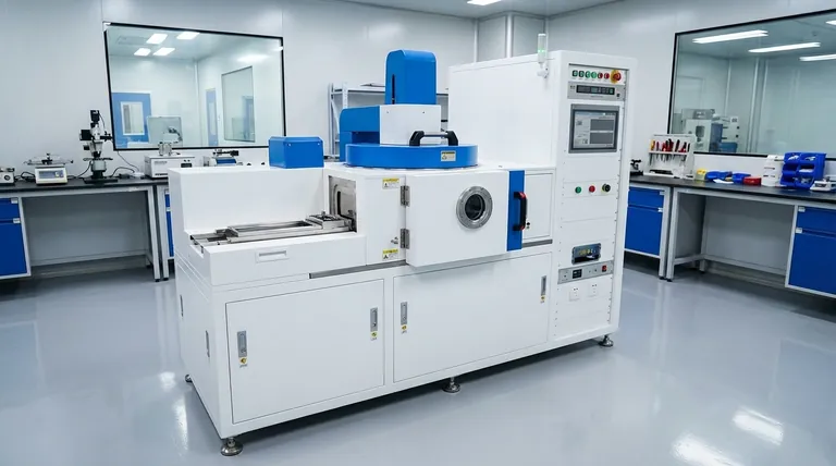
Ready to integrate thermal evaporation into your lab workflow? KINTEK specializes in lab equipment and consumables, providing reliable thermal evaporation systems tailored to your research or production needs. Whether you're depositing metal layers for electronics or optics, our expertise ensures precise film quality and process efficiency. Contact us today to discuss your project and discover the right solution for your laboratory!
Visual Guide
Related Products
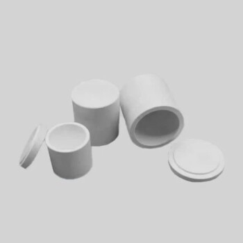
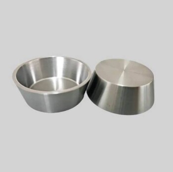
- Molybdenum Tungsten Tantalum Evaporation Boat for High Temperature Applications
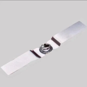
- Aluminized Ceramic Evaporation Boat for Thin Film Deposition
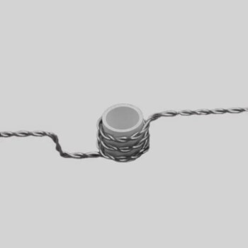
- Evaporation Boat for Organic Matter
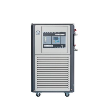
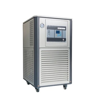
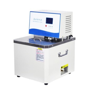
- 5L Heating Chilling Circulator Cooling Water Bath Circulator for High and Low Temperature Constant Temperature Reaction
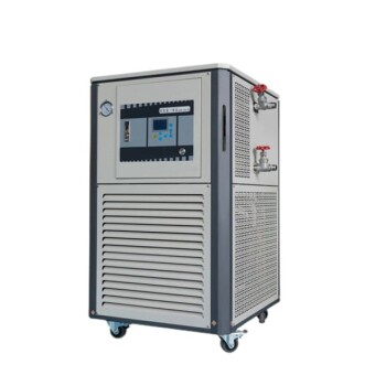
- 20L Heating Chilling Circulator Cooling Water Bath Circulator for High and Low Temperature Constant Temperature Reaction
People Also Ask
- How does a molybdenum evaporation source function in H2S for MoS2 synthesis? Master Reactive Film Deposition
- How source material is evaporated during deposition? A Guide to Resistive vs. E-Beam Methods
- What is the source of evaporation for thin film? Choosing Between Thermal and E-Beam Methods
- What is the widely used boat made of in thermal evaporation? Choosing the Right Material for High-Purity Deposition
- What are the sources of thermal evaporation? A Guide to Resistive vs. E-Beam Heating