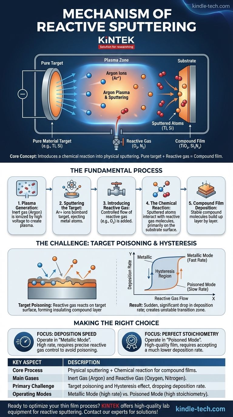
At its core, reactive sputtering is a vacuum deposition technique that intentionally introduces a chemical reaction into a physical sputtering process. Instead of simply depositing a pure material from a target, a reactive gas like oxygen or nitrogen is added to the chamber. This gas reacts with the sputtered atoms as they travel to and land on the substrate, forming a completely new compound material—such as an oxide or nitride—as a thin film.
The crucial insight is that reactive sputtering allows you to create high-quality compound films (like ceramics) using a simple, pure metallic target. It merges the physical process of sputtering with the chemical process of compound formation, offering precise control over the final film's composition.
The Fundamental Process: From Plasma to Film
To understand the mechanism, it's best to break it down into a sequence of events occurring inside the vacuum chamber.
Step 1: Plasma Generation with an Inert Gas
The process begins in a high-vacuum chamber. An inert gas, almost always Argon (Ar), is introduced at a very low pressure.
A high voltage is applied, which ionizes the argon gas, stripping electrons from the argon atoms and creating a plasma—a glowing soup of positive argon ions (Ar+) and free electrons.
Step 2: Sputtering the Target
The target, made of the pure source material (e.g., titanium, silicon), is given a large negative voltage. This attracts the positively charged argon ions from the plasma.
These energetic ions bombard the target surface with significant force. This physical impact is strong enough to knock out, or "sputter," individual atoms from the target material, ejecting them into the chamber.
Step 3: Introducing the Reactive Gas
This is the step that defines the process. A second gas, a reactive gas like Oxygen (O₂) or Nitrogen (N₂), is bled into the chamber at a precisely controlled flow rate.
The amount of this reactive gas is critical and is carefully balanced against the argon flow and the pumping speed of the vacuum system.
Step 4: The Chemical Reaction
As the sputtered metal atoms travel from the target to the substrate, they encounter and interact with the molecules of the reactive gas.
The primary chemical reaction occurs on the surface of the substrate itself. As metal atoms arrive, they immediately combine with reactive gas molecules that are also present on the surface, forming a stable compound. For example, a sputtered Titanium (Ti) atom reacts with Oxygen (O₂) to form Titanium Dioxide (TiO₂).
Step 5: Compound Film Deposition
The newly formed compound molecules (e.g., TiO₂, Si₃N₄) build up layer by layer on the substrate. This process continues until a thin film of the desired thickness and composition is achieved.
By controlling the partial pressure of the reactive gas, you can precisely tune the stoichiometry (the chemical ratio of elements) of the resulting film.
Understanding the Trade-offs: The Challenge of Target Poisoning
While powerful, reactive sputtering has a critical process challenge that every operator must manage. This is often referred to as the "hysteresis effect."
The Core Problem: Target Poisoning
If the flow of the reactive gas is too high, it doesn't just react on the substrate. It begins to react with and form a compound layer on the surface of the target itself.
This is known as target poisoning. For example, in a titanium process, the surface of the pure titanium target becomes coated in a thin layer of insulating titanium dioxide.
The Consequence: A Sudden Drop in Rate
The "sputter yield"—the number of atoms ejected per incoming ion—is dramatically lower for a compound or ceramic than it is for a pure metal.
When the target becomes poisoned, the deposition rate suddenly and significantly plummets. The process shifts from a fast, "metallic mode" to a very slow, "poisoned" or "reactive mode."
Navigating the Hysteresis Loop
This behavior creates two stable operating regimes with a highly unstable transition zone between them. Moving from the fast metallic mode to the slow poisoned mode happens at a specific reactive gas flow.
However, to get back to the fast metallic mode, you must reduce the gas flow to a much lower point than where poisoning first occurred. This lag is called the hysteresis effect, and it makes operating in the desirable (but unstable) transition region extremely difficult without advanced process controls.
Making the Right Choice for Your Goal
Success in reactive sputtering depends entirely on managing the delicate balance between deposition rate, process stability, and final film quality. Your primary objective determines your ideal operating point.
- If your primary focus is deposition speed: You must operate in the "metallic mode," using just enough reactive gas to ensure a full reaction on the substrate without poisoning the target.
- If your primary focus is perfect stoichiometry: You may need to operate in the "poisoned mode," accepting a much lower deposition rate as the trade-off for a fully reacted, high-quality film.
- If your primary focus is process stability and quality: Advanced feedback systems that monitor plasma emission or voltage are often used to "walk the line" of the unstable transition region, maximizing rate while ensuring stoichiometry.
Mastering this technique is a matter of precisely controlling a chemical reaction within a high-energy physical deposition environment.
Summary Table:
| Key Aspect | Description |
|---|---|
| Core Process | Physical sputtering combined with a chemical reaction to form compound films (e.g., oxides, nitrides). |
| Main Gases | Inert Gas (Argon) and Reactive Gas (Oxygen, Nitrogen). |
| Primary Challenge | Target poisoning, which causes a hysteresis effect and a drop in deposition rate. |
| Operating Modes | Metallic Mode (high rate) and Poisoned Mode (high stoichiometry). |
Ready to perfect your thin film deposition process? KINTEK specializes in high-quality lab equipment and consumables for reactive sputtering and other vacuum deposition techniques. Our experts can help you select the right system and optimize your process for maximum deposition rate, stability, and film quality. Contact our team today to discuss your laboratory's specific needs!
Visual Guide
Related Products
- Spark Plasma Sintering Furnace SPS Furnace
- Chemical Vapor Deposition CVD Equipment System Chamber Slide PECVD Tube Furnace with Liquid Gasifier PECVD Machine
- RF PECVD System Radio Frequency Plasma-Enhanced Chemical Vapor Deposition RF PECVD
- Customer Made Versatile CVD Tube Furnace Chemical Vapor Deposition Chamber System Equipment
- Vacuum Induction Melting Spinning System Arc Melting Furnace
People Also Ask
- What is the pressure for spark plasma sintering? A Guide to Optimizing SPS Parameters
- What are the advantages of CAMI/SPS for W-Cu composite preparation? Reduce cycles from hours to seconds.
- What technical advantages does a Spark Plasma Sintering (SPS) furnace offer for LZP ceramics? Enhance Ionic Conductivity
- What is the process fundamentals of spark plasma sintering? Achieve Rapid, High-Density Material Consolidation
- What is the difference between spark plasma sintering and flash sintering? A Guide to Advanced Sintering Methods


