In e-beam evaporation, the tooling factor is a critical calibration constant that reconciles the thickness measured by an in-process monitor with the actual film thickness deposited on your substrate. It is not an inherent physical property of the evaporation process itself, but rather a correction value specific to your chamber's geometry, the material being deposited, and your monitoring setup.
The tooling factor is the essential bridge between measurement and reality in thin-film deposition. It is a calculated ratio that corrects for the geometric and material differences between your thickness sensor and your actual part, ensuring the final film meets its required specification.
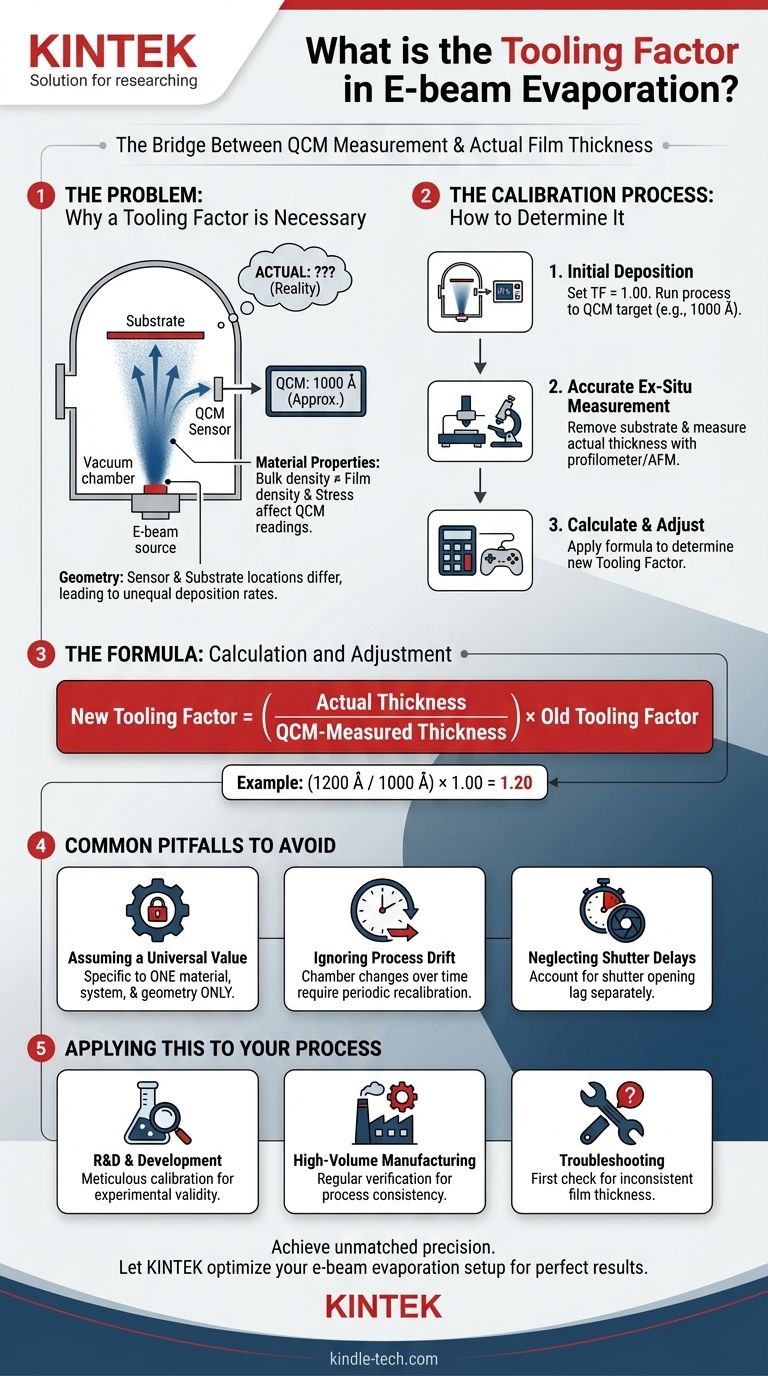
Why a Tooling Factor is Necessary
To control film thickness during deposition, most e-beam systems use a Quartz Crystal Microbalance (QCM). However, the QCM's measurement is an indirect approximation that requires correction.
The Role of the Quartz Crystal Microbalance (QCM)
A QCM sensor is a small, disc-shaped quartz crystal that oscillates at a stable resonant frequency.
As material from the e-beam source deposits onto the crystal's surface, its mass increases, causing the oscillation frequency to drop.
The system's controller measures this frequency change and, using pre-programmed material properties like density, calculates a "thickness" value in real time.
The Problem of Geometry
The QCM sensor cannot be placed in the exact same location as your substrate. It is typically positioned off to the side to monitor the deposition plume.
Because the evaporated material radiates from the source in a cone-like shape, the deposition rate at the QCM's location is almost always different from the rate at the substrate's location.
The tooling factor directly compensates for this geometric difference in deposition rates.
The Problem of Material Properties and Stress
The QCM controller calculates thickness based on the bulk density of the source material. However, the density of a thin film can differ from its bulk counterpart.
Furthermore, internal stress within the depositing film can impose a mechanical load on the QCM crystal, altering its frequency and introducing error into the thickness calculation. The tooling factor helps correct for these material-dependent effects.
How to Determine the Tooling Factor
The tooling factor must be empirically determined for each unique combination of material, chamber, and substrate fixturing. It is a straightforward calibration procedure.
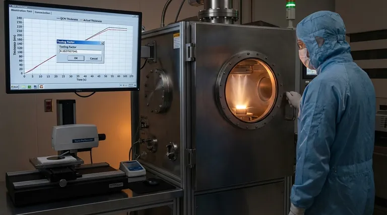
Step 1: Initial Deposition
First, ensure your QCM is programmed with the correct material density and set the tooling factor in your controller to a default value, typically 1.00 (or 100%).
Run a deposition process, aiming for a specific thickness as reported by the QCM (e.g., 1000 Å).
Step 2: Accurate Ex-Situ Measurement
After the deposition is complete, remove the substrate and measure the actual film thickness using a precise, independent instrument.
Common measurement tools include a stylus profilometer, an atomic force microscope (AFM), or an ellipsometer. This measurement is your ground truth.
Step 3: Calculation and Adjustment
Calculate the new tooling factor using the following formula:
New Tooling Factor = (Actual Thickness / QCM-Measured Thickness) * Old Tooling Factor
For example, if the QCM reported 1000 Å but your profilometer measured 1200 Å, the new tooling factor would be (1200 / 1000) * 1.00 = 1.20. You would then enter this value into your deposition controller for all future runs with this exact setup.
Common Pitfalls to Avoid
Accurate tooling is fundamental to process control. Misunderstanding its role can lead to significant and costly errors in production.
Assuming a Universal Value
The tooling factor is highly specific. It is only valid for a single material in a single deposition system with a fixed geometry.
You cannot use the tooling factor from one machine on another, or even for a different material in the same machine. A new calibration is required for any change in material or physical setup.
Ignoring Process Drift
The tooling factor is not a "set it and forget it" parameter. Over time, the characteristics of your chamber can change.
Flakes from previous depositions can fall, the QCM crystal degrades with use, and the position of the e-beam spot on the source material can shift. These factors can alter the deposition geometry and require periodic recalibration.
Neglecting Shutter Delays
The QCM responds instantly to material flux, but there is a physical delay as the shutter opens and the flux stabilizes. Sophisticated controllers have settings to account for this, which should be configured alongside the tooling factor for maximum accuracy.
Applying This to Your Process
Your approach to the tooling factor should align with your operational goals.
- If your primary focus is process development or R&D: Meticulously calibrate the tooling factor for every new material and geometry. This establishes a reliable baseline and is a non-negotiable step for experimental validity.
- If your primary focus is high-volume manufacturing: Implement a regular schedule for verifying and, if necessary, recalibrating the tooling factor. This acts as a critical process control check to prevent drift and ensure product consistency.
- If you are troubleshooting inconsistent film thickness: An incorrect or outdated tooling factor is a common root cause. Verifying your tooling factor should be one of the first steps in your diagnostic procedure.
Mastering the tooling factor is the key to transforming e-beam evaporation from a complex process into a precise and repeatable manufacturing technique.
Summary Table:
| Aspect | Description |
|---|---|
| Purpose | A correction factor to match QCM sensor readings to actual substrate thickness. |
| Typical Starting Value | 1.00 (or 100%) |
| Key Influences | Chamber geometry, material being deposited, monitoring setup. |
| Calculation Formula | New TF = (Actual Thickness / QCM Thickness) × Old TF |
| Measurement Tools | Stylus profilometer, ellipsometer, atomic force microscope (AFM). |
Achieve unmatched precision in your thin-film deposition processes. The correct tooling factor is critical for R&D validity and manufacturing consistency. KINTEK specializes in providing the high-quality lab equipment and expert support that laboratories like yours depend on. Let our team help you optimize your e-beam evaporation setup for perfect results every time.
Contact us today to discuss your specific application needs!
Visual Guide
Related Products
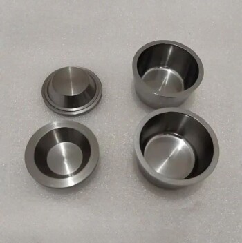
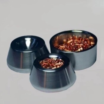
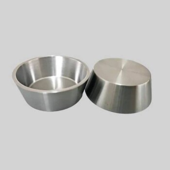
- Electron Beam Evaporation Coating Oxygen-Free Copper Crucible and Evaporation Boat
- Electron Beam Evaporation Coating Tungsten Crucible and Molybdenum Crucible for High Temperature Applications
- Electron Beam Evaporation Coating Gold Plating Tungsten Molybdenum Crucible for Evaporation
- E Beam Crucibles Electron Gun Beam Crucible for Evaporation
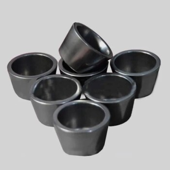
- High Purity Pure Graphite Crucible for Electron Beam Evaporation
People Also Ask
- What are the applications of e-beam evaporation? Achieve High-Purity Coatings for Optics & Electronics
- What is e-beam evaporation used for? Precision Coating for Optics, Aerospace & Electronics
- What is e-beam evaporation? Achieve High-Purity Thin Film Deposition for Your Lab
- What is the voltage of e-beam evaporation? Achieve Precise Thin-Film Deposition
- How is an electron beam evaporator cooled during deposition? Essential Thermal Management for Stable Processes