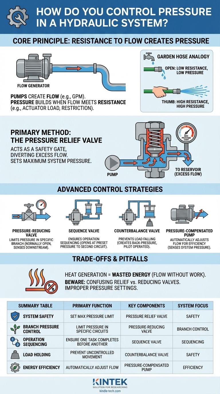
At its core, pressure in a hydraulic system is controlled by a pressure relief valve. This component acts as a safety gate, setting the maximum pressure the system can reach by diverting excess pump flow back to the reservoir. While the pump creates fluid flow, it is the resistance to this flow—from an actuator doing work or a restriction in a line—that actually generates the pressure.
The fundamental concept to grasp is that you don't directly control pressure; you control the resistance to flow. The pump's job is to create flow, and pressure control valves are the tools used to manage the pressure that results from resisting that flow.
The Core Principle: Resistance to Flow Creates Pressure
To effectively control pressure, you must first abandon the common misconception that pumps "create" pressure. They do not. They create movement of fluid.
The Pump's Role: The Flow Generator
A hydraulic pump is a flow-generating device. Whether it's a gear, vane, or piston pump, its primary function is to take fluid from the reservoir and push it into the system at a certain rate (e.g., gallons per minute).
Resistance: The Source of Pressure
Pressure only builds when this flow meets resistance. This resistance can come from a heavy load on a hydraulic cylinder, the torque required to turn a hydraulic motor, or even a partially closed valve.
The Garden Hose Analogy
Think of a garden hose with the water turned on. With the end open, water flows freely at very low pressure. When you place your thumb over the end (adding resistance), the pressure inside the hose builds, and the water sprays out at high velocity. The pump (the faucet) didn't change; only the resistance to its flow did.
The Primary Method: The Pressure Relief Valve
The most common and critical pressure control component is the pressure relief valve. It serves as both a primary control and a crucial safety device.
How It Works
A simple, direct-acting relief valve contains a poppet or ball held shut by an adjustable spring. As long as the system pressure is below the spring's setting, the valve remains closed.
When pressure exceeds the spring setting, it forces the poppet off its seat. This opens a path for the pump's flow to return directly to the tank at low pressure, preventing any further rise in system pressure.
Setting Maximum System Pressure
The primary job of the pressure relief valve is to act as the system's "governor." It is set to a pressure slightly above the maximum required working pressure to protect components like hoses, pumps, and actuators from dangerous over-pressurization.
Advanced Pressure Control Strategies
Beyond the main relief valve, other specialized valves are used to control pressure in specific parts of a circuit or for specific functions.
Pressure-Reducing Valves
A pressure-reducing valve is used to limit pressure in one specific branch of a circuit. Unlike a relief valve which is normally closed, a reducing valve is normally open and senses pressure downstream. When the downstream pressure reaches its setting, the valve begins to close, restricting flow to maintain the set reduced pressure.
Sequence Valves
A sequence valve ensures that one operation completes before another one begins. It remains closed until the pressure in its primary circuit reaches a preset level (e.g., a clamp cylinder fully extends). Once that pressure is met, the valve opens and directs flow to a secondary circuit (e.g., a drill motor).
Counterbalance Valves
A counterbalance valve is used to prevent a vertical cylinder or other overrunning load from falling due to gravity. It creates back-pressure in the cylinder's return line, holding the load in place. The valve only opens to allow the cylinder to lower when pilot pressure is applied from the opposite line.
Pressure-Compensated Pumps
A highly efficient method of control involves a variable-displacement, pressure-compensated pump. This type of pump can automatically adjust its own flow output. It senses system pressure and, as it approaches the "compensator" setting, the pump reduces its flow to just what is needed to maintain that pressure, drastically reducing wasted energy and heat generation compared to a fixed pump dumping flow over a relief valve.
Understanding the Trade-offs and Pitfalls
Controlling pressure effectively requires acknowledging the compromises involved, particularly regarding efficiency and complexity.
Heat Generation is Wasted Energy
Whenever hydraulic fluid flows from a high-pressure area to a low-pressure area without performing work (such as across a relief valve), the pressure energy is converted directly into heat. This represents wasted electrical or engine power and often requires a dedicated cooling system to manage.
Confusing Relief vs. Reducing Valves
A common mistake is using these valves interchangeably. Remember: a relief valve limits pressure upstream of itself by diverting flow to the tank. A pressure-reducing valve limits pressure downstream of itself by restricting flow to the sub-circuit.
Improper Pressure Settings
Setting a main relief valve too high can lead to catastrophic component failure. Setting it too low will prevent the machine from doing its required work. Precise and careful adjustment based on system design specifications is critical.
Matching the Control to Your Goal
The right pressure control strategy depends entirely on what you are trying to achieve in your hydraulic system.
- If your primary focus is system safety: Your main pressure relief valve is the most important component; ensure it is properly sized and set slightly above the maximum working pressure.
- If your primary focus is energy efficiency: A pressure-compensated pump is the ideal solution, followed by circuits that use unloading valves.
- If you need to control pressure in a specific part of a circuit: A pressure-reducing valve is the correct tool for that branch.
- If you need to sequence operations based on pressure: A sequence valve provides simple, reliable automation for a clamp-then-work cycle.
- If you need to safely hold a suspended load: A counterbalance valve is the non-negotiable component for preventing uncontrolled movement.
By understanding that you are managing resistance, not creating pressure, you gain true control over the power and precision of your hydraulic system.
Summary Table:
| Control Method | Primary Function | Key Component |
|---|---|---|
| System Safety | Set maximum pressure limit | Pressure Relief Valve |
| Branch Pressure Control | Limit pressure in specific circuits | Pressure-Reducing Valve |
| Operation Sequencing | Ensure one task completes before another | Sequence Valve |
| Load Holding | Prevent uncontrolled movement of suspended loads | Counterbalance Valve |
| Energy Efficiency | Automatically adjust flow to maintain pressure | Pressure-Compensated Pump |
Optimize Your Hydraulic System Performance with KINTEK
Struggling with hydraulic pressure control, heat generation, or system inefficiencies? KINTEK specializes in providing high-quality lab equipment and hydraulic components that deliver precise pressure management and energy efficiency. Our experts can help you select the right valves, pumps, and systems to enhance your laboratory's operational safety and reduce energy waste.
Contact us today to discuss your specific hydraulic needs and discover how our solutions can improve your system's reliability and performance!
Visual Guide