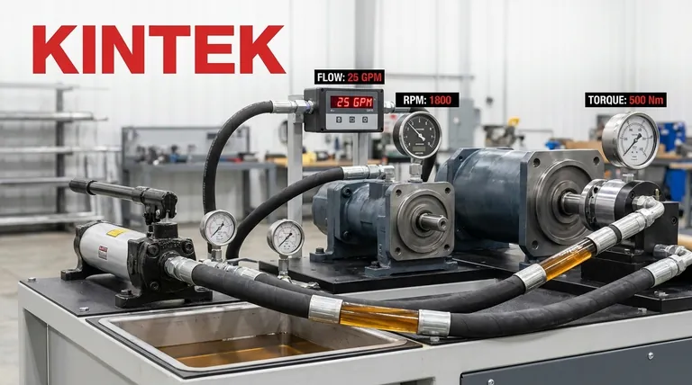
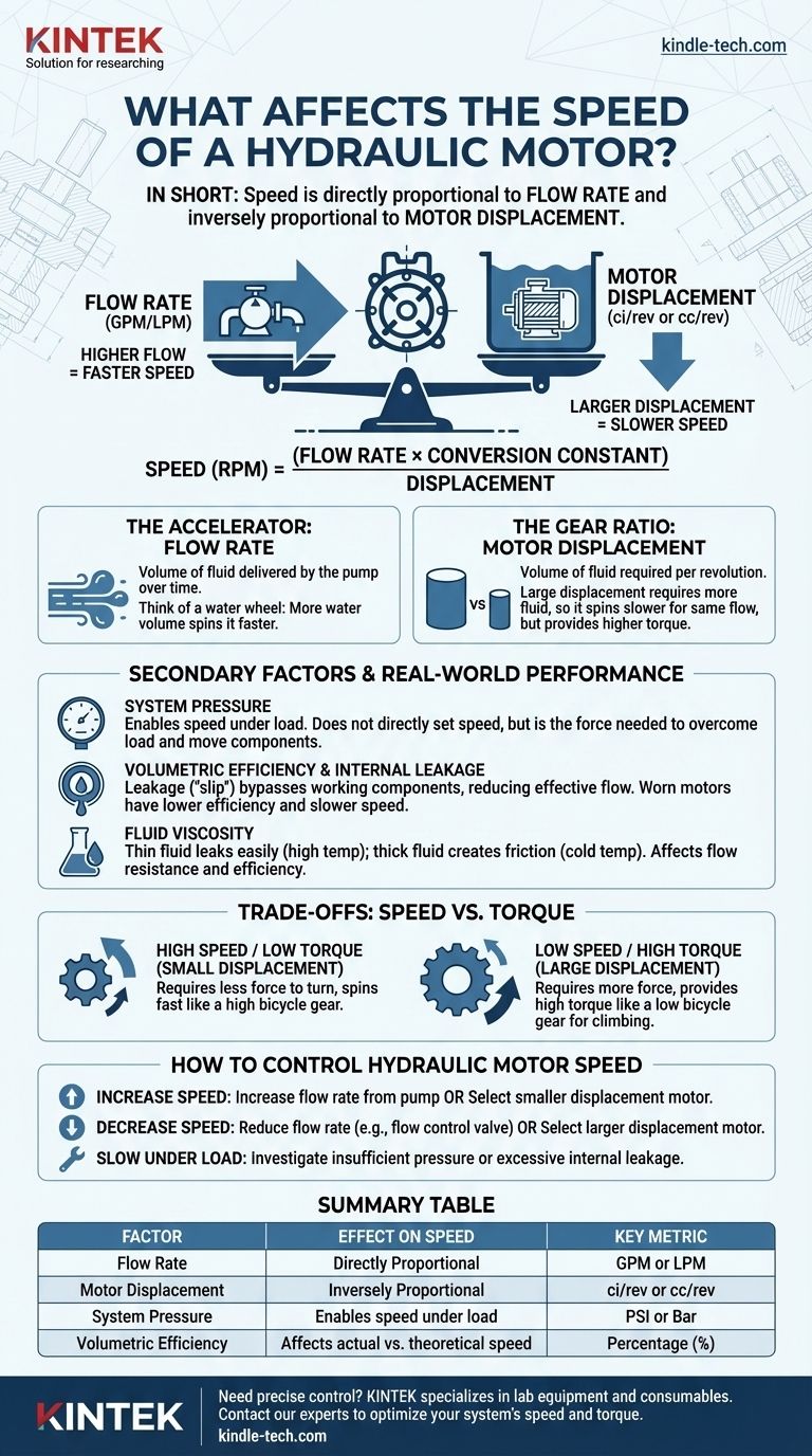
In short, the speed of a hydraulic motor is determined by two primary factors. It is directly proportional to the flow rate of the fluid supplied to it and inversely proportional to the motor's displacement. Essentially, more fluid flow makes the motor spin faster, while a larger motor (requiring more fluid per rotation) will spin slower for the same amount of flow.
The core principle is a simple balance: motor speed is the direct result of how quickly you can fill the motor's internal volume. The pump's flow rate dictates the supply, while the motor's displacement dictates the demand for each rotation.
The Two Primary Factors Governing Speed
To truly control or troubleshoot a hydraulic motor, you must understand the distinct roles of flow and displacement. They are the fundamental inputs that define its performance.
Flow Rate (GPM or LPM): The Accelerator
The flow rate is the volume of hydraulic fluid that the pump delivers to the motor over a specific period, typically measured in gallons per minute (GPM) or liters per minute (LPM).
Think of it as the volume of water hitting a water wheel. A greater volume of water (higher flow rate) will cause the wheel to spin faster. In a hydraulic system, the pump generates this flow.
Motor Displacement (ci/rev or cc/rev): The Gear Ratio
Displacement is the volume of fluid a motor requires to complete one single revolution. This is a fixed physical characteristic of the motor, measured in cubic inches per revolution (ci/rev) or cubic centimeters per revolution (cc/rev).
A motor with a large displacement is like an engine with large cylinders. It requires more fluid to turn over once, so for a given flow rate, it will rotate more slowly but produce higher torque. Conversely, a small displacement motor spins very quickly for the same flow but produces less torque.
The Fundamental Formula
These two factors are linked by a core formula:
Speed (RPM) = (Flow Rate x Conversion Constant) / Displacement
The constant simply reconciles the units (e.g., converting gallons to cubic inches and minutes to revolutions). The key takeaway is the direct relationship: if you double the flow, you double the speed. If you double the displacement, you halve the speed.
Secondary Factors and Real-World Performance
While flow and displacement set the theoretical speed, other system variables determine how a motor performs under actual working conditions.
System Pressure
Pressure does not directly set the motor's speed, but it is the force required to overcome the load. If system pressure is insufficient to handle the load on the motor shaft, the motor will stall or slow down significantly, regardless of the flow rate.
Pressure is the "enabler" of work. It provides the force needed for the flow to actually move the motor's internal components against resistance.
Volumetric Efficiency and Internal Leakage
No motor is perfectly sealed. Internal leakage, or "slip," is the small amount of fluid that bypasses the motor's working components, leaking from the high-pressure inlet side directly to the low-pressure outlet side.
This leaked fluid does no useful work and effectively represents a loss of flow. A new motor might be 95% efficient, but as components wear over time, leakage increases, volumetric efficiency drops, and the motor's speed will decrease, especially under high load.
Fluid Viscosity
The viscosity (thickness) of the hydraulic fluid also plays a role. Fluid that is too thin (often due to high temperatures) will leak more easily, reducing volumetric efficiency and speed.
Conversely, fluid that is too thick can create excess friction and flow resistance, also potentially hindering performance, particularly in cold conditions.
Understanding the Trade-offs: Speed vs. Torque
It is impossible to evaluate motor speed in isolation. The most critical trade-off in any hydraulic motor application is between speed and torque.
The Inverse Relationship
For a given system pressure and flow, speed and torque are inversely proportional. You can configure a system for high speed or high torque, but you cannot maximize both with the same components.
A small displacement motor is a "high-speed, low-torque" device. A large displacement motor is a "low-speed, high-torque" device.
An Analogy: Bicycle Gears
Think of a bicycle's gears. The rider's power is the hydraulic system's pressure and flow.
- A low gear (like a large displacement motor) makes it easy to pedal up a hill (high torque) but your legs spin slowly and the bike moves at a low speed.
- A high gear (like a small displacement motor) requires much more force to pedal (low torque) but allows the bike to reach a very high speed on a flat road.
How to Control Hydraulic Motor Speed
Your approach to controlling speed depends entirely on your design goals and operational needs.
- If your primary focus is increasing speed: You must either increase the flow rate from the pump or select a motor with a smaller displacement.
- If your primary focus is decreasing speed: You must either reduce the flow rate (often with a flow control valve) or select a motor with a larger displacement.
- If your motor is running slow under load: Investigate two main causes: insufficient system pressure to overcome the load, or excessive internal leakage due to worn components.
By mastering the interplay between flow, displacement, and system pressure, you can precisely engineer and diagnose the performance of any hydraulic system.
Summary Table:
| Factor | Effect on Speed | Key Metric |
|---|---|---|
| Flow Rate | Directly Proportional | GPM or LPM |
| Motor Displacement | Inversely Proportional | ci/rev or cc/rev |
| System Pressure | Enables speed under load | PSI or Bar |
| Volumetric Efficiency | Affects actual vs. theoretical speed | Percentage (%) |
Need precise control for your hydraulic applications? KINTEK specializes in lab equipment and consumables, serving laboratory needs. Our expertise can help you select the right components to optimize your system's speed and torque. Contact our experts today to discuss your specific requirements and achieve superior performance.
Visual Guide
Related Products
- Automatic High Temperature Heated Hydraulic Press Machine with Heated Plates for Lab
- Heated Hydraulic Press Machine with Heated Plates for Vacuum Box Laboratory Hot Press
- Manual High Temperature Heated Hydraulic Press Machine with Heated Plates for Lab
- Automatic Laboratory Hydraulic Press for XRF & KBR Pellet Press
- Automatic Laboratory Hydraulic Pellet Press Machine for Lab Use
People Also Ask
- What role does a heated hydraulic press play in Cold Sintering (CSP)? Enhancing LATP-Halide Densification
- Why is the heating function of a laboratory hydraulic press essential for MEA assembly in DEFC? Optimize Cell Bonding
- What are heated hydraulic presses used for? Molding Composites, Vulcanizing Rubber, and More
- What technical conditions does a heated hydraulic press provide for PEO batteries? Optimize Solid-State Interfaces
- What is the core function of a laboratory heated hydraulic press in CSP? Revolutionize Low-Temp Ceramic Sintering