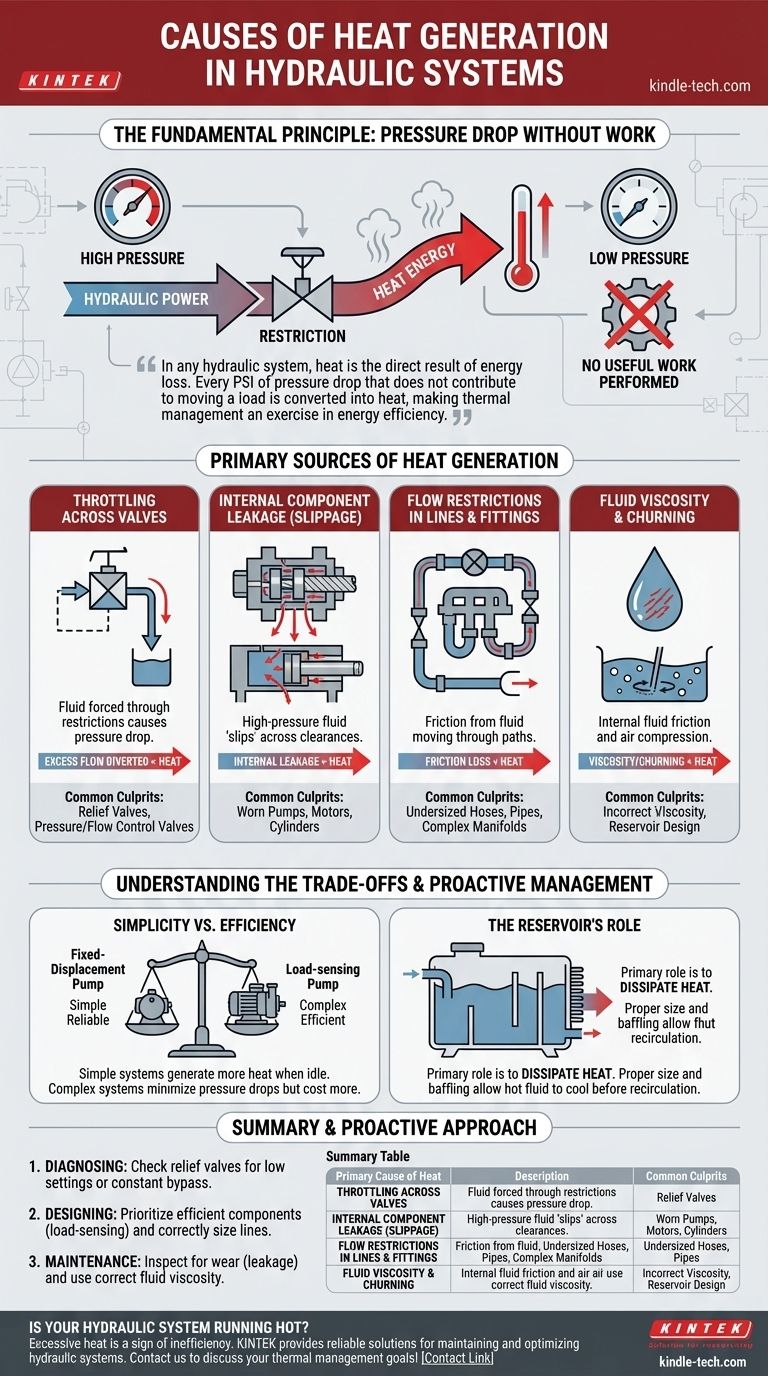
In any hydraulic system, heat is the direct result of energy loss. This occurs whenever hydraulic fluid experiences a pressure drop without performing useful work, or when mechanical friction is present. These inefficiencies convert hydraulic power or mechanical energy directly into thermal energy, which is then absorbed by the fluid.
The core principle to understand is that heat is not a mysterious byproduct; it is a measurable symptom of wasted energy. Every pound per square inch (PSI) of pressure drop that does not contribute to moving a load is converted into heat, making thermal management fundamentally an exercise in energy efficiency.
The Fundamental Principle: Pressure Drop Without Work
All hydraulic systems are designed to transmit power. This power is a function of flow and pressure. When fluid flows across a restriction from a high-pressure area to a low-pressure area without moving an actuator, the potential energy is lost.
According to the laws of thermodynamics, this energy cannot be destroyed, so it is converted directly into heat. Think of it like vigorously rubbing your hands together—the friction and resistance create warmth. The same principle applies to fluid molecules being forced through a restriction.
Primary Sources of Heat Generation
Heat is generated at every point of inefficiency in a circuit. While some sources are minor, several key areas are responsible for the majority of heat in a typical system.
Throttling Across Valves
Valves that control pressure or flow by throttling are significant heat sources. When fluid is forced through a restricted opening in the valve, its pressure drops.
The most common culprit is a relief valve. When the system pressure reaches the valve's setting, it opens to divert excess flow back to the tank. The entire pressure drop across this valve becomes heat. A system that constantly operates "over relief" will run extremely hot.
Internal Component Leakage (Slippage)
No hydraulic component is perfectly efficient. Pumps, motors, and cylinders all have small, engineered clearances between their moving parts.
High-pressure fluid inevitably leaks or "slips" across these clearances to the low-pressure side. This internal leakage is a pressure drop that performs no work, generating heat directly within the component. As components wear, these clearances increase, leading to more slippage and higher heat generation.
Flow Restrictions in Lines and Fittings
Every component in the fluid's path creates a degree of friction. Fluid moving through hoses, pipes, and fittings experiences pressure loss due to this friction.
Undersized lines, numerous sharp 90-degree bends, or overly complex manifolds force the pump to work harder, increasing pressure drop and generating excess heat throughout the system.
Fluid Viscosity and Churning
The fluid itself is a source of heat. As the fluid is pumped, its internal molecules create friction. If the fluid's viscosity is too high for the operating temperature, the energy required to push it through the system increases, generating more heat.
Additionally, fluid churning within the reservoir can generate heat through friction and compression of entrained air bubbles.
Understanding the Trade-offs
It is impossible to create a hydraulic system that generates zero heat. The goal is to minimize unnecessary heat by making conscious design and maintenance choices.
Simplicity vs. Efficiency
A simple system using a fixed-displacement pump and a relief valve is inexpensive and reliable. However, any time the actuators are not moving, the pump's full flow goes over the relief valve at maximum pressure, generating a tremendous amount of heat.
A more complex pressure-compensated or load-sensing system is far more efficient. It reduces pump flow when demand is low, minimizing pressure drops and heat generation. This efficiency comes at the cost of higher upfront component expense and complexity.
The Role of the Reservoir
The reservoir's primary thermal role is to dissipate heat. A small or poorly designed reservoir can worsen a heat problem. If the hot return fluid does not have enough time to cool before being drawn back into the pump suction line, the system's baseline temperature will continuously climb.
A properly sized reservoir provides adequate surface area for cooling and uses baffles to ensure hot return oil follows a long path before re-entering the circuit.
A Proactive Approach to Thermal Management
Understanding the sources of heat empowers you to diagnose problems and design more robust systems. Your approach should be tailored to your specific goal.
- If your primary focus is diagnosing an overheating system: Check for a relief valve that is set too low or is constantly bypassing fluid, as this is the most common and significant source of excess heat.
- If your primary focus is designing an efficient new system: Prioritize efficient components, such as a load-sensing pump, and correctly size all lines and fittings to minimize flow restrictions from the start.
- If your primary focus is routine maintenance: Regularly inspect the system for signs of component wear (which increases internal leakage) and ensure you are using the correct hydraulic fluid viscosity for your climate and duty cycle.
Ultimately, controlling heat in a hydraulic system is synonymous with maximizing its energy efficiency.
Summary Table:
| Primary Cause of Heat | Description | Common Culprits |
|---|---|---|
| Throttling Across Valves | Pressure drop across a restriction without performing work. | Relief valves, pressure/flow control valves. |
| Internal Component Leakage | High-pressure fluid slipping past internal clearances. | Worn pumps, motors, and cylinders. |
| Flow Restrictions | Friction from fluid moving through lines and fittings. | Undersized hoses, pipes, and complex manifolds. |
| Fluid Viscosity & Churning | Energy lost to internal fluid friction and air compression. | Incorrect fluid viscosity, reservoir design. |
Is your hydraulic system running hot? Excessive heat is a sign of energy inefficiency and can lead to premature component failure. KINTEK specializes in lab equipment and consumables, providing reliable solutions for maintaining and optimizing hydraulic systems in laboratory and industrial settings. Our expertise helps you minimize energy loss and maximize performance. Contact us today via our [#ContactForm] to discuss how we can support your thermal management and efficiency goals!
Visual Guide
Related Products
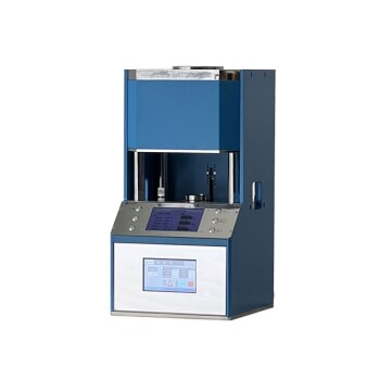
- Automatic High Temperature Heated Hydraulic Press Machine with Heated Plates for Lab
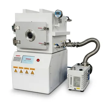
- Heated Hydraulic Press Machine with Heated Plates for Vacuum Box Laboratory Hot Press
- Automatic Laboratory Hydraulic Press for XRF & KBR Pellet Press
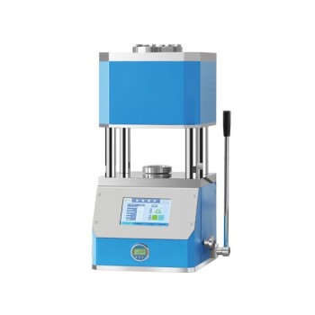
- Manual High Temperature Heated Hydraulic Press Machine with Heated Plates for Lab
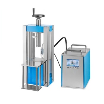
- Laboratory Hydraulic Press Split Electric Lab Pellet Press
People Also Ask
- What is a heated hydraulic press used for? Essential Tool for Curing, Molding, and Laminating
- What technical conditions does a heated hydraulic press provide for PEO batteries? Optimize Solid-State Interfaces
- What are heated hydraulic presses used for? Molding Composites, Vulcanizing Rubber, and More
- What is the core function of a laboratory heated hydraulic press in CSP? Revolutionize Low-Temp Ceramic Sintering
- Why is a heated hydraulic press used for warm pressing NASICON green tapes? Optimize Your Solid Electrolyte Density