To be direct, there is no single deposition rate for sputtering. The rate is not a fixed constant but a highly variable outcome that depends on the specific material being deposited, the type of sputtering system used, and the precise process parameters. While DC sputtering of some pure metals can achieve high deposition rates, the actual value can range from a few angstroms to hundreds of nanometers per minute.
The critical takeaway is that sputtering deposition rate is not an inherent property of the technique itself, but a controllable variable. Understanding the factors that govern this rate is the key to optimizing the process for either maximum throughput or superior film quality.
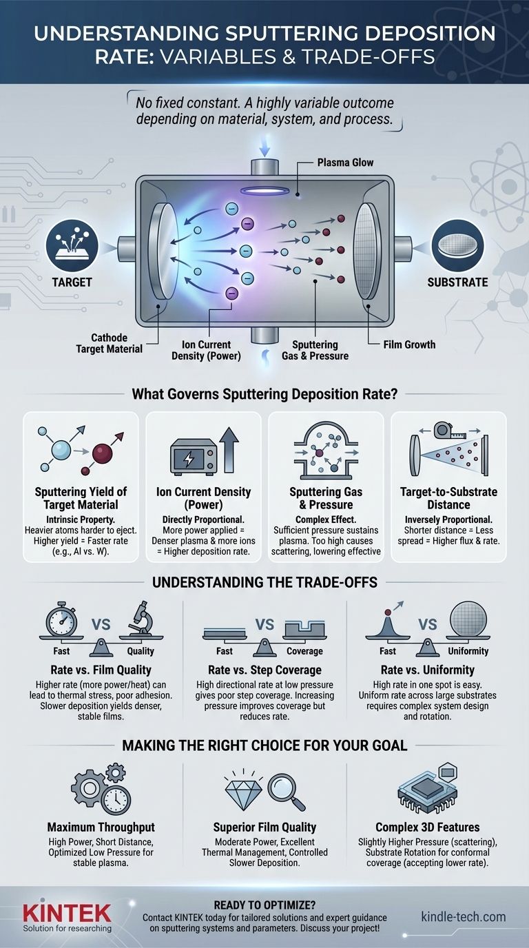
What Governs Sputtering Deposition Rate?
The speed at which a film grows in a sputtering system is a direct result of several interacting physical factors. Mastering your process means understanding how to manipulate each one.
The Sputtering Yield of the Target Material
Sputtering yield is the most fundamental factor. It defines the number of atoms ejected from the target surface for each single high-energy ion that strikes it.
This yield is an intrinsic property of the material. Heavier target atoms (like gold or tungsten) are generally harder to eject than lighter ones (like aluminum or titanium), resulting in different inherent sputtering rates under the same conditions.
The Ion Current Density at the Target
The deposition rate is directly proportional to the ion current density—the number of ions bombarding a specific area of the target per second.
More power applied to the cathode (the target) creates a denser plasma, which in turn increases the flow of ions to the target. In simple terms, more power equals a higher deposition rate. This is the most common lever used to control the speed of the process.
The Sputtering Gas and Chamber Pressure
The process operates in a vacuum chamber backfilled with an inert gas, typically Argon. The pressure of this gas plays a dual role.
First, a sufficient pressure (e.g., 1-100 mTorr) is needed to sustain the plasma that generates the ions. However, if the pressure is too high, sputtered atoms will collide with many gas molecules on their way to the substrate. This scattering effect reduces the number of atoms arriving directly, thereby lowering the effective deposition rate.
The Target-to-Substrate Distance
The geometry of the chamber is critical. As the distance between the target and the substrate increases, the flux of sputtered atoms reaching the substrate decreases.
This is due to the simple geometric effect of atoms spreading out over a larger area, similar to how a flashlight beam becomes dimmer as you move it further from a wall. A shorter distance generally leads to a higher rate.
Understanding the Trade-offs
Pursuing the maximum possible deposition rate often involves compromises in other critical areas of film quality. It is essential to understand these trade-offs to achieve your desired outcome.
Rate vs. Film Quality
Aggressively increasing the deposition rate by raising power also increases the energy and heat delivered to the substrate. This can introduce thermal stress into the film, cause poor adhesion, or even damage sensitive substrates. A slower, more controlled deposition often yields a denser and more stable film structure.
Rate vs. Step Coverage
A very high, directional deposition rate achieved at low pressure creates a "line-of-sight" path for sputtered atoms. While fast, this can result in poor step coverage, where the film is much thinner on the sidewalls of microscopic features than on the top surfaces. Increasing pressure can improve coverage by scattering atoms, but this comes at the direct expense of a lower deposition rate.
Rate vs. Uniformity
Achieving a high deposition rate in one spot is simple; achieving a high and uniform rate across a large substrate is a significant engineering challenge. System design, including magnetron configuration and substrate rotation, is critical for balancing the competing goals of speed and film thickness uniformity.
Making the Right Choice for Your Goal
Your optimal deposition rate is determined by your primary objective. Use these guidelines to steer your process decisions.
- If your primary focus is maximum throughput: Utilize high-power DC sputtering for conductive metals, minimize the target-to-substrate distance, and fine-tune pressure to be just high enough to sustain a stable plasma.
- If your primary focus is superior film quality: Employ moderate power levels, ensure excellent thermal management of the substrate, and allow for a slower, more controlled deposition to grow a dense, low-stress film.
- If your primary focus is coating complex 3D features: Intentionally use a slightly higher gas pressure to induce scattering, and combine this with substrate rotation to ensure conformal step coverage, accepting that this will reduce the overall deposition rate.
Ultimately, controlling the deposition rate is about deliberately balancing these interconnected process variables to meet your specific technical and economic goals.
Summary Table:
| Factor | Effect on Deposition Rate |
|---|---|
| Target Material (Sputtering Yield) | Intrinsic property; lighter metals (Al) typically sputter faster than heavier ones (W). |
| Power / Ion Current Density | Directly proportional; more power = higher rate. |
| Gas Pressure | Complex effect; too high a pressure causes scattering and reduces the effective rate. |
| Target-to-Substrate Distance | Inversely proportional; shorter distance = higher rate. |
Ready to optimize your sputtering process for maximum throughput, superior film quality, or perfect step coverage? The experts at KINTEK specialize in lab equipment and consumables, providing tailored solutions for your specific laboratory needs. We can help you select the right system and parameters to achieve your precise deposition goals. Contact us today to discuss your project!
Visual Guide
Related Products
- Chemical Vapor Deposition CVD Equipment System Chamber Slide PECVD Tube Furnace with Liquid Gasifier PECVD Machine
- Customer Made Versatile CVD Tube Furnace Chemical Vapor Deposition Chamber System Equipment
- HFCVD Machine System Equipment for Drawing Die Nano-Diamond Coating
- RF PECVD System Radio Frequency Plasma-Enhanced Chemical Vapor Deposition RF PECVD
- 915MHz MPCVD Diamond Machine Microwave Plasma Chemical Vapor Deposition System Reactor
People Also Ask
- How expensive is chemical vapor deposition? Understanding the True Cost of High-Performance Coating
- What are the advantages of chemical vapor deposition? Achieve Superior Thin Films for Your Lab
- What types of substrates are used in CVD to facilitate graphene films? Optimize Graphene Growth with the Right Catalyst
- What is the chemical vapor deposition growth process? Build Superior Thin Films from the Atom Up
- What is plasma enhanced chemical vapor deposition PECVD equipment? A Guide to Low-Temperature Thin Film Deposition