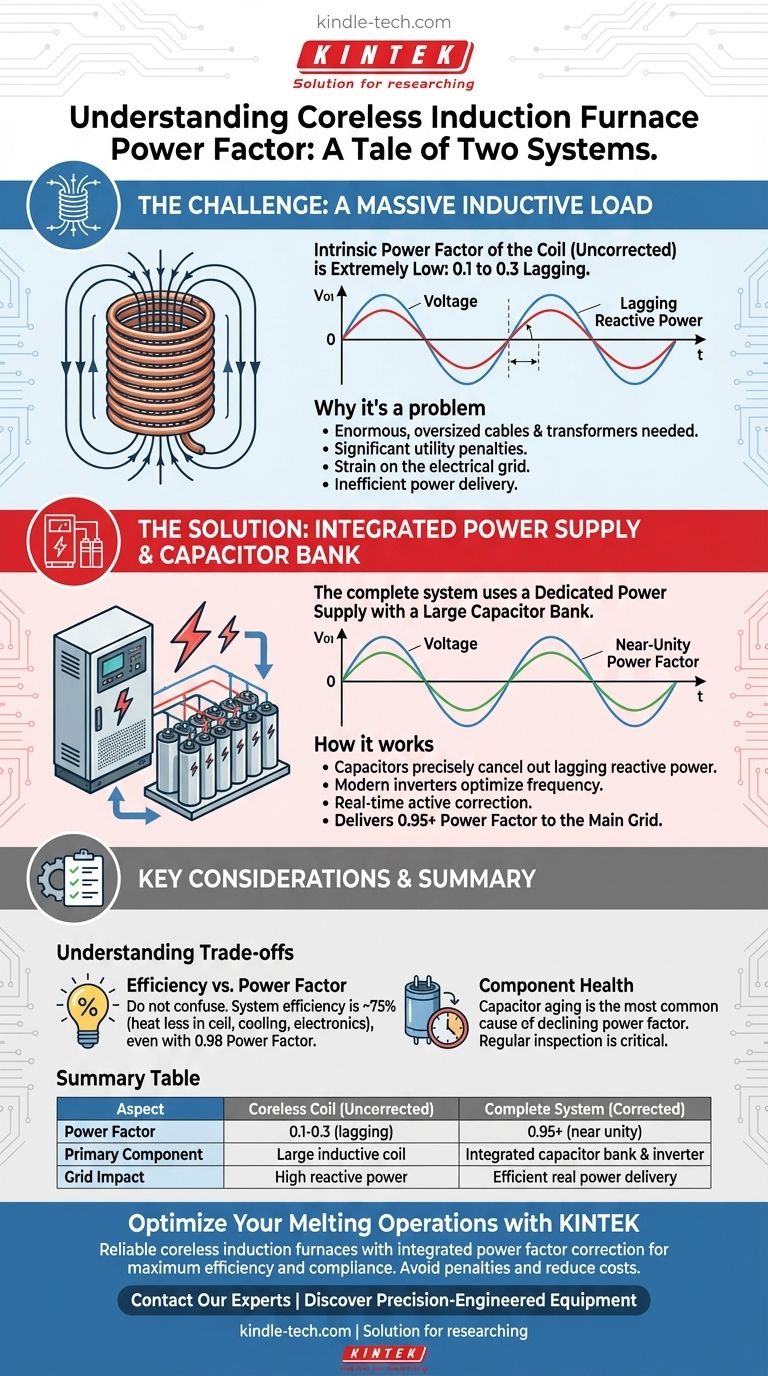
The intrinsic power factor of a coreless induction furnace coil is extremely low, typically in the range of 0.1 to 0.3 lagging. This is a direct result of its design as a large, air-cored inductor. However, a complete furnace system includes a dedicated power supply with a large capacitor bank specifically designed to correct this, delivering a final power factor of 0.95 or higher to the main electrical grid.
A coreless induction furnace is a tale of two systems. While the furnace coil itself is a highly inductive load with a very poor power factor, the complete power supply unit uses capacitor banks to actively correct this, presenting a much healthier, near-unity power factor to the electrical grid.
The Core Electrical Challenge: A Massive Inductive Load
To understand the furnace's power factor, we must first look at its fundamental component: the coil. This is the source of the electrical challenge that the rest of the system is built to solve.
The Role of the Induction Coil
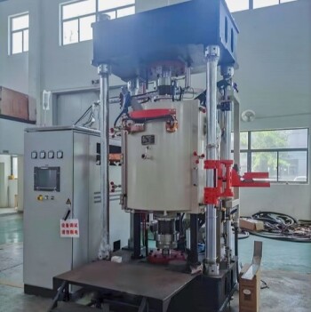
A coreless induction furnace works by passing a strong alternating current through a large helical copper coil. This creates a powerful, changing magnetic field that induces immense electrical currents directly within the metal charge, generating heat.
From an electrical perspective, this large coil is a massive inductor. Inductive loads inherently resist changes in current, causing the current waveform to lag behind the voltage waveform.
Defining Power Factor
Power factor is the measure of how effectively incoming power is converted into useful work. A perfect power factor of 1.0 means voltage and current are perfectly in sync.
A low, or lagging, power factor means a significant portion of the current is flowing back and forth in the system without performing useful work. This "reactive power" still loads the wires and transformers, but doesn't contribute to melting the metal.
The Consequence of a Poor Power Factor
An uncorrected power factor of 0.1 to 0.3 would be disastrous for any industrial facility. It would require enormous, oversized cables and transformers to handle the excessive current.
Furthermore, utility companies often impose significant financial penalties for facilities with poor power factors because it puts a strain on the entire electrical grid.
The Solution: The Integrated Power Supply
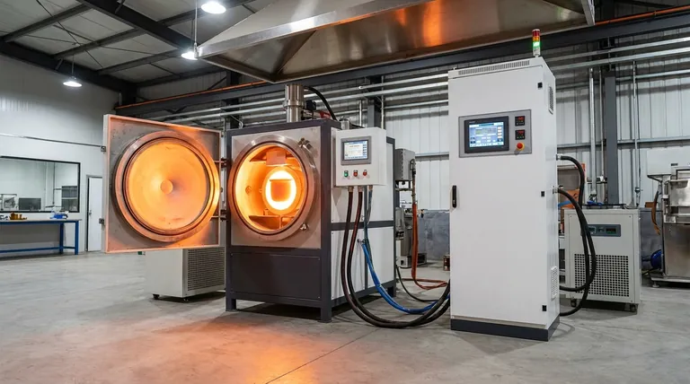
No coreless induction furnace operates by connecting its coil directly to the grid. It relies on a sophisticated power supply unit that converts and conditions the power while correcting its fundamental flaws.
The Function of the Capacitor Bank
The power supply's primary tool for correction is a large capacitor bank. Capacitors are the electrical opposite of inductors; they create a leading power factor where current leads voltage.
By precisely sizing and switching these capacitors in parallel with the furnace coil, the power supply cancels out the coil's lagging reactive power. This brings the overall system's power factor back into alignment, approaching a near-perfect 1.0.
Modern Inverter Technology
Modern furnace power supplies use inverters to convert the standard 3-phase grid frequency (50/60 Hz) to the optimal frequency needed for melting (from 50 Hz to 10 kHz).
These solid-state systems continuously monitor the load and adjust the power factor correction in real-time. This ensures a high power factor is maintained even as the furnace cycles through different power levels, from initial startup to full-power melting and holding.
The System as a Whole
For all practical purposes, the "power factor of the furnace" is the power factor measured at the main connection point to your facility. The internal, uncorrected power factor of the coil is an engineering problem that the manufacturer has already solved with the integrated power supply.
Understanding the Trade-offs and Realities
While modern systems are highly effective, it's crucial to distinguish between related concepts and be aware of potential issues.
Efficiency vs. Power Factor
Do not confuse power factor with power efficiency. The references note a coreless furnace has a power efficiency of approximately 75%.
This means that for every 100 kW of real power consumed, about 75 kW becomes heat in the metal, while 25 kW is lost to waste heat in the coil, cooling systems, and power electronics. A system can have a near-perfect power factor (0.98) but still have 75% efficiency.
Partial Load Operation
While modern systems strive to maintain a high power factor across the operating range, it is often optimized for full-power operation. At very low power (e.g., holding a melt overnight), the power factor may be slightly lower than at peak production.
Component Health and Aging
The capacitor bank is a critical component. As capacitors age, they can fail, reducing the system's ability to correct the power factor. A gradual decline in your plant's overall power factor can be an early indicator that the furnace's capacitor bank requires inspection and maintenance.
Key Considerations for Your Operation
Your approach to this topic depends on your primary role and responsibilities.
- If your primary focus is electrical system design: Concentrate on the specifications of the complete power supply unit, ensuring it can deliver a corrected power factor of 0.95 or better to the grid under your typical operating loads.
- If your primary focus is operational cost: Understand that while power factor is crucial for avoiding utility penalties, the furnace's overall energy efficiency (around 75%) is what primarily dictates your melting cost per ton.
- If your primary focus is maintenance and reliability: Regularly inspect the health of the capacitor bank, as its degradation is the most common cause of a declining system power factor and can lead to operational faults.
Ultimately, managing a coreless induction furnace is about understanding it as a complete electrical system, where the undesirable properties of the coil are actively managed by the intelligence of the power supply.
Summary Table:
| Aspect | Coreless Furnace Coil (Uncorrected) | Complete Furnace System (Corrected) |
|---|---|---|
| Power Factor | 0.1 - 0.3 (lagging) | 0.95+ (near unity) |
| Primary Component | Large inductive coil | Integrated capacitor bank & inverter |
| Grid Impact | High reactive power, potential penalties | Efficient real power delivery |
| Key Consideration | Internal design challenge | Managed by power supply unit |
Optimize your melting operations with KINTEK's advanced induction furnace solutions.
KINTCEL specializes in lab equipment and consumables, providing reliable coreless induction furnaces with integrated power factor correction to ensure maximum efficiency and compliance. Our systems deliver near-unity power factor (0.95+) to the grid, helping you avoid utility penalties and reduce operational costs.
Ready to enhance your laboratory's melting efficiency? Contact our experts today to discuss your specific needs and discover how KINTEK can support your laboratory's success with precision-engineered equipment.
Visual Guide
Related Products
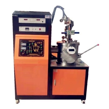
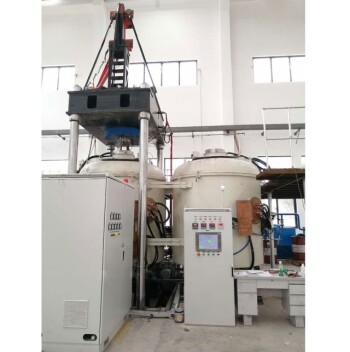
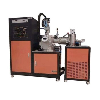
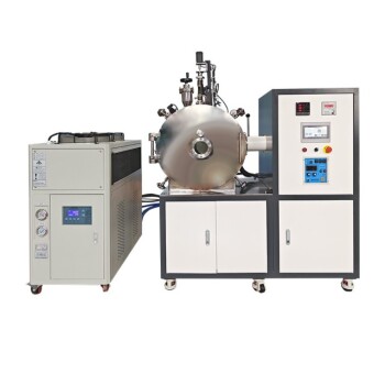
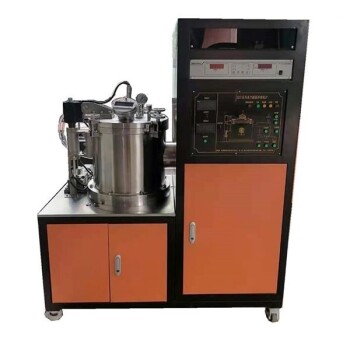
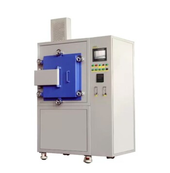
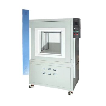
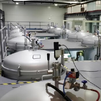
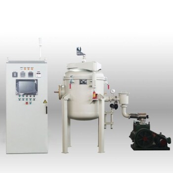
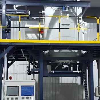
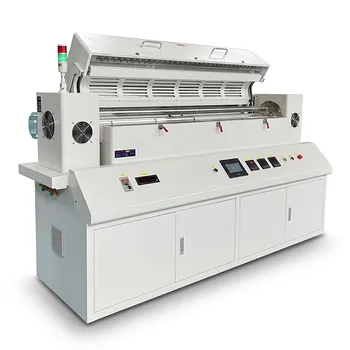
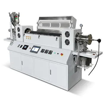
- Non Consumable Vacuum Arc Induction Melting Furnace
- 600T Vacuum Induction Hot Press Furnace for Heat Treat and Sintering
- Vacuum Arc Induction Melting Furnace
- Lab-Scale Vacuum Induction Melting Furnace
- Vacuum Heat Treat Furnace and Levitation Induction Melting Furnace
People Also Ask
- What is the function of vacuum arc melting equipment? Creating High-Purity Ferrochrome (CrFe) Alloys
- What is the temperature range of the induction melting furnace? Find the Right Heat for Your Metals
- What is the primary function of a vacuum arc melting furnace in RHEA preparation? Achieving Extreme Thermal Fusion
- What are the advantages of induction melting furnace? Achieve Purity, Efficiency, and Safety
- How do vacuum induction or arc melting furnaces facilitate the synthesis of U-Al-C MAX phases? Precision Heat & Purity