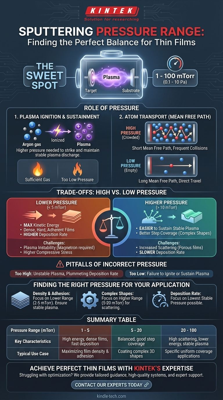
In sputtering, the working pressure is a critical parameter that directly governs the entire deposition process. The typical operating pressure for sputtering is a fine vacuum, generally falling between 1 and 100 millitorr (mTorr). This range, equivalent to approximately 0.1 to 10 Pascals (Pa), is the sweet spot required to both generate a stable plasma and control how atoms travel from the source target to your substrate.
The optimal sputtering pressure is a delicate balance. It must be low enough to allow sputtered atoms to travel freely to the substrate, yet high enough to sustain the stable plasma discharge needed to eject those atoms from the target in the first place.
The Role of Pressure in the Sputtering Process
Understanding why this pressure range is so important requires looking at two key physical phenomena: generating the plasma and transporting the atoms.
Igniting and Sustaining the Plasma
Sputtering begins by introducing an inert gas, typically Argon, into the vacuum chamber. A high voltage is applied, which strips electrons from the gas atoms and creates a plasma—an energized cloud of ions and electrons.
This plasma can only be ignited and maintained if there are enough gas atoms present to sustain the chain reaction. If the pressure is too low, the plasma will be unstable or extinguish completely.
Mean Free Path and Atom Transport
Once the plasma is active, its positive ions bombard the target material, knocking atoms loose. These sputtered atoms must then travel to the substrate to form the thin film.
The key concept here is the mean free path: the average distance a particle travels before colliding with another.
At higher pressures, the chamber is crowded with gas atoms. The mean free path is very short, causing sputtered atoms to collide frequently on their way to the substrate.
At lower pressures, the chamber is emptier. The mean free path is much longer, allowing sputtered atoms to travel in a more direct, "line-of-sight" path to the substrate with fewer collisions.
Impact on Film Quality and Deposition Rate
This relationship between pressure and mean free path directly impacts the final film.
Higher pressure leads to more scattering. This reduces the energy of the sputtered atoms arriving at the substrate, which can result in a more porous, less dense film with lower adhesion. It also significantly slows down the deposition rate.
Lower pressure allows atoms to arrive with higher energy. This generally produces denser, harder, and more adherent films. Because fewer atoms are scattered away from the substrate, the deposition rate is also higher.
Understanding the Trade-offs: High vs. Low Pressure
Choosing a pressure is not about finding a single "correct" number, but about making an informed compromise based on your goals.
The Case for Lower Pressure (< 5 mTorr)
Operating at the low end of the range offers significant advantages. It maximizes the kinetic energy of sputtered atoms, which is excellent for creating dense, high-quality films. It also provides the fastest possible deposition rate.
However, maintaining a stable plasma at very low pressures can be difficult without advanced techniques like magnetron sputtering. It can also lead to higher compressive stress within the film.
The Case for Higher Pressure (> 10 mTorr)
Using a higher pressure makes it much easier to strike and sustain a uniform, stable plasma across the entire target.
The increased scattering, while reducing film density, can sometimes be beneficial for coating complex, three-dimensional shapes, as the atoms arrive at the substrate from a wider range of angles.
The Pitfalls of Incorrect Pressure
Operating too far outside the optimal range leads to failure.
If pressure is too high, the plasma may become unstable, and the deposition rate will plummet as most sputtered atoms are scattered before ever reaching the substrate.
If pressure is too low, you simply won't be able to ignite or sustain the plasma required for the process to work at all.
Finding the Right Pressure for Your Application
The ideal pressure is specific to your material, your system's geometry, and the desired properties of your final film. Use the following as a guide.
- If your primary focus is maximum film density and adhesion: Start at the lower end of the viable range (e.g., 2-5 mTorr) and ensure your system can maintain a stable plasma.
- If your primary focus is coating complex shapes with good step coverage: Consider operating at a slightly higher pressure (e.g., 5-20 mTorr) to take advantage of increased atomic scattering.
- If your primary focus is maximizing deposition rate: Aim for the lowest stable pressure your system allows, as this minimizes in-flight collisions and ensures a direct path to the substrate.
Ultimately, the ideal pressure is an empirical parameter, tuned to balance the competing needs of plasma stability, deposition rate, and the final properties of your film.
Summary Table:
| Pressure Range (mTorr) | Key Characteristics | Typical Use Case |
|---|---|---|
| 1 - 5 | High energy atoms, dense films, fast deposition | Maximizing film density and adhesion |
| 5 - 20 | Balanced scattering and energy, good step coverage | Coating complex 3D shapes |
| 20 - 100 | High scattering, lower energy, stable plasma | Specific applications requiring uniform coverage |
Achieve Perfect Thin Films with KINTEK's Expertise
Struggling to find the optimal sputtering pressure for your specific materials and substrate? The delicate balance between plasma stability and film quality requires precise control and expert knowledge.
At KINTEK, we specialize in laboratory sputtering equipment and consumables, helping researchers and engineers like you overcome deposition challenges. Our team can provide:
- Tailored pressure optimization guidance for your application
- High-quality sputtering systems with precise pressure control
- Expert technical support for achieving superior film properties
Let's optimize your sputtering process together. Contact our experts today to discuss your specific requirements and discover how KINTEK's solutions can enhance your thin film research and production.
Visual Guide
Related Products
- Spark Plasma Sintering Furnace SPS Furnace
- Vacuum Induction Melting Spinning System Arc Melting Furnace
- Chemical Vapor Deposition CVD Equipment System Chamber Slide PECVD Tube Furnace with Liquid Gasifier PECVD Machine
- Customer Made Versatile CVD Tube Furnace Chemical Vapor Deposition Chamber System Equipment
People Also Ask
- Why are Spark Plasma Sintering (SPS) furnaces or hot presses utilized in the preparation of Li3PS4 solid electrolytes?
- What is the theory of spark plasma sintering? A Guide to Rapid, Low-Temperature Densification
- What is the process fundamentals of spark plasma sintering? Achieve Rapid, High-Density Material Consolidation
- What technical advantages does a Spark Plasma Sintering (SPS) furnace offer for LZP ceramics? Enhance Ionic Conductivity
- What are the advantages of CAMI/SPS for W-Cu composite preparation? Reduce cycles from hours to seconds.


