Purpose of Filter Press Pilot Testing
Table of Contents
- Purpose of Filter Press Pilot Testing
- Description of HPL300, HPL470, and HPL500 pilot filter presses
- Recessed chamber and membrane filter press configurations
- Basic test procedure and observations
- Filter Cloths
- Chemicals and Filter Aids
- Test Procedure
- Safety Issues
- Special Notes for the HPL470 and HPL500 Filter Presses
Filter press pilot testing serves the purpose of collecting data necessary for accurately sizing a full-scale filter press system. This data includes various parameters such as cake solids, cake density, total processing time, processing time for each step, slurry feed solids, slurry pH, chemical conditioning dosages, and maximum operating pressure for each process step. Additionally, other data like filtrate suspended solids, slurry pH, and specific chemical analysis required by the process may also be collected.
Data collection for sizing a full-scale filter press system
During the filter press pilot testing, the following steps are typically involved:
-
Preparation: The slurry or slurry is prepared, and the filter press is set up with the correct plates and filter cloth.
-
Filling and Filtration: The pump is turned on, and the press is filled. Filtrate is observed, and timing starts. Filtrate samples are taken at regular intervals. The test continues until both low flow and maximum pressure conditions are reached for filtration.
-
Additional Steps for Membrane Test: If it is a membrane test, optional steps like cake wash, membrane squeeze, and air blow down may be performed after reaching the maximum pressure.
-
Cake Removal and Analysis: Once the test is finished, the press is opened, and the filter cake is removed. Cake samples are taken for analysis, including measurements of cake solids, cake density, cake thickness, and other required parameters. It is important to note the cake release during this process and observe the overall surface condition of the filter cloth.
-
Recessed Chamber Test for Pilot Filter Presses: For pilot filter presses using recessed chamber plates, the cloth is installed on the filter plates, and the plates are put in the filter press frame. The press is closed and pressurized to the proper pressure. Filtrate valves are opened, and the feed pump and polymer feed pump are started. The test continues as mentioned above.
By conducting filter press pilot testing, businesses can gather essential data to determine the appropriate size and configuration for a full-scale filter press system. This ensures optimal filtration efficiency and productivity in various industrial processes.
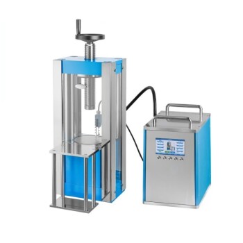
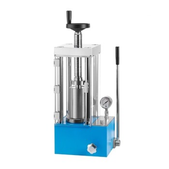
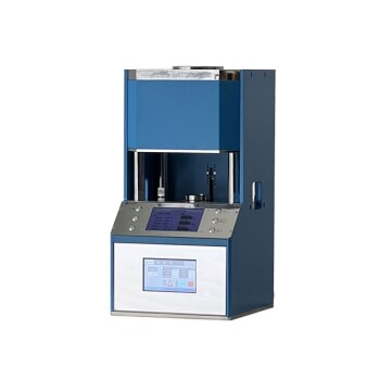
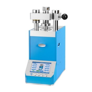
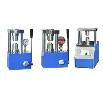
Description of HPL300, HPL470, and HPL500 pilot filter presses
The HPL300, HPL470, and HPL500 pilot filter presses are "sidebar" filter presses each with a manual hydraulic pump. These filter presses consist of a frame, hydraulic system, and filter plates with filter cloths. The HPL500 can use either 470 mm x 470 mm filter plates or 500 mm x 500 mm filter plates, while the HPL470 can only use 470 mm x 470 mm plates. The HPL300 uses 300 mm x 300 mm plates. Other equipment needed for a test includes pumps and mixing tanks with mixers.
Recessed chamber and membrane filter press configurations
There are two basic filter press configurations: recessed chamber and membrane. Both the HPL470 and HPL500 pilot presses are suitable for all testing for both configurations. A recessed chamber test requires the filter press, feed pump(s), and a mixing tank with a mixer. A membrane test requires all the equipment needed for a recessed chamber test, plus a source of compressed gas for membrane squeeze and the necessary equipment to control the membrane squeeze. The HPL300 is suitable for recessed chamber tests and basic membrane tests without cake washing.
Basic test procedure and observations
The basic test starts with preparing the slurry or slurry as required and installing the correct plates and filter cloth in the filter press. Once the press and sample are ready, the pump is turned on and the press is filled. Filtrate will be seen when the press is filled, and timing and taking filtrate samples begin. The test continues until both the low flow and maximum pressure conditions have been reached for filtration.
For a recessed chamber test, the test is ended at this point. For a membrane test, it is continued with optional steps such as cake wash, membrane squeeze, and optional air blow down. Once the test is finished, the press is opened, the filter cake is removed, and cake samples are taken. During the cake release, it is important to note how the cake released and the overall surface condition of the filter cloth. Cake release is normally somewhat better on a larger press, but if there is poor release on the test unit, the release on the larger unit will also be poor.
During the test, it is essential to collect data such as cake solids, cake density, total processing time, processing time for each step, slurry feed solids, slurry pH, actual chemical conditioning dosages, and maximum operating pressure for each process step. Additional data that is often collected includes filtrate suspended solids, slurry pH, and specific chemical analysis required by the process.
In summary, the HPL300, HPL470, and HPL500 pilot filter presses are versatile equipment for conducting filter press pilot testing. They can be used for both recessed chamber and membrane configurations, depending on the specific testing requirements. The test procedure involves preparing the slurry, filling the press, and monitoring the filtration process until the desired conditions are reached. Collecting accurate data during the test is crucial for sizing a full-scale filter press system.
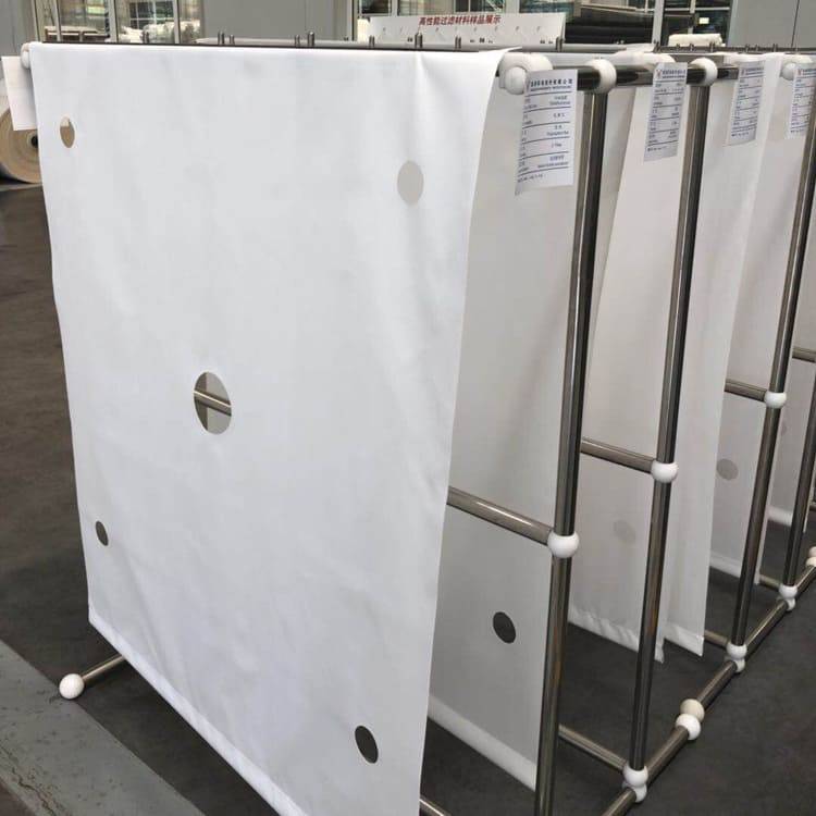
Filter Cloths
When it comes to selecting a filter cloth for your filter press, there are two main criteria to consider: the initial quality of the filtrate and cake release. The initial quality of the filtrate refers to how clean the filtrate is when it first passes through the cloth. On process applications, it is common to prioritize improved initial filtrate quality, even if it means slightly poorer cake release. On the other hand, for most waste applications, it is common to prioritize improved cake release, even if it means slightly dirtier initial filtrate. Ultimately, the selection of filter cloth involves a combination of experience and trial and error.
Another important factor to consider is the chemical compatibility of the fabric material with the slurry. Different fabrics have different levels of resistance to various chemicals, so it's important to choose a cloth that can withstand the specific chemicals present in your slurry. This is crucial to ensure the longevity and effectiveness of the filter cloth.
In addition to the filter cloth, there are also chemicals and filter aids that can be used to enhance the filtration process. Chemical conditioning involves adding chemicals to the slurry to improve filtration efficiency. However, it's important to note that for most process applications, chemical conditioning is not possible due to the risk of contaminating the product.
Some common chemicals used for chemical conditioning include ferric chloride solution, which is commercially available with a concentration of 36% and a density of 1.378 gm/ml. The proper dosages of these chemicals can be determined through testing.
Filter presses are widely used in various industries and applications for liquid/solid separation. They can be customized to meet specific needs, such as filtration capacity, number of chambers, filter plate size, and materials of construction. Industries that commonly use filter presses include food and beverage processing, chemical manufacturing, mining, power generation, aggregates, asphalt and cement production, steel mills, and municipal plants.
Overall, filter cloths play a crucial role in the filtration process of a filter press. By considering the criteria of initial filtrate quality, cake release, and chemical compatibility, you can select the right filter cloth for your specific application needs.
Chemicals and Filter Aids
Determination of chemicals for conditioning
The chemicals used for chemical conditioning in filtration processes are determined through tests to determine the proper chemical dosages. It is important to note that for most process applications, chemical conditioning is not possible due to contamination of the product.
Use of ferric chloride solution and hydrated lime
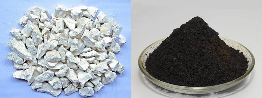
When using ferric chloride and lime for slurry, it is recommended to add the ferric chloride first and mix well before adding the lime and mixing well. Ferric chloride solution of known concentration and density is commonly used. A commercially available ferric chloride solution typically has a concentration of 36% and a density of 1.378 gm/ml.
Hydrated lime, chemical grade with an analysis of 90 - 95% as Ca(OH)2 or 68 - 72% available CaO, is usually made into a 10% w/w slurry to add to the slurry. The density of the 10% slurry is 1.08 gm/ml.
Addition of filter aids and other inorganic chemicals
Filter aids are typically added as slurries, usually at a concentration of 10% w/w. Other inorganic chemicals may be added as either solutions or slurries, depending on the specific chemical being used.
Test Procedure
Slurry and General Preparations
When conducting tests, it is important to mimic the expected process conditions as closely as possible, especially with initial pump flow rates. However, this may be challenging due to the varying sizes of the feed pumps used.
Filter Cloths
The selection of filter cloths is based on two criteria: the initial quality of the filtrate and cake release. In process applications, it is common to prioritize improved initial filtrate quality over cake release. Conversely, in most waste applications, slightly dirty initial filtrate may be accepted for improved cake release. The selection of cloth is typically based on experience and trial and error. Additionally, the chemical compatibility of the fabric material with the slurry is an important consideration.
Ideal Water Content in Ethanol Extraction
During the extraction of solvents, such as in ethanol extraction, the ideal water content ranges from 70% to 95%. Water additives serve as catalysts for oxidizing pathogenic cell membranes and can help reduce costs and combustion hazards. In the case of FCC grade solvents, which require pure water when dilution is needed, microfiltered water with a purity level of 0.2 micron and de-ionized water are used to ensure a product free of heavy metals, volatiles, pyrogens, and microbes.
Material Characteristics
When analyzing a product to ensure it meets desired specifications, several material characteristics are considered: flowability, compression strength, bulk density, crushing strength, chemical analysis, and gas sampling and monitoring. These characteristics help determine if the product meets the desired specifications and aid in the process scale-up. Process data, such as residence time, kiln slope, temperature requirements, kiln rotating speed, emissions, and feed rate, can also contribute to achieving the desired product specifications.
Condensate Traps
Condensate traps are used to remove condensed liquids from the vacuum suction line. They work through adsorption of vapors to material media or cooling surfaces placed in the vacuum line, or a combination of both. Regular servicing is required to drain the condensed liquids from condensate traps. Some traps have automatic drain systems and automatic pump shut-off when the traps reach and pass high-level points. Water traps can be clear or have sight glasses to indicate when draining is required.
Inlet Filters and Water Traps
Inlet filters with paper, poly, or activated carbon, along with water traps, help keep vacuum oil uncontaminated for longer periods of service. These filters are essential in avoiding particulates from entering the pump, which can score the walls and reduce efficiency. Additionally, particulates inside the pump can cause damage and lead to seizing, failure, and long repair times. It is recommended to have a backup pump or access to an experienced pump repair shop nearby.
Test Procedure
Preparation of slurry
To start the test procedure for the pilot filter presses, you need to install the cloth on the filter plates and put the plates in the filter press frame. Close the press and pressurize the hydraulic cylinder to the proper pressure. It's important to note that the procedure for the bench press is outlined in Section 6.4.2. Additionally, calibrate the pumps as required per manufacturer's instructions.
Recessed Chamber Test procedure and observations
- Close the press and make sure the closing hydraulic pressure is reached before tightening the locking ring.
- Close the bottom filtrate valves and open the top filtrate valves. Ensure that the air blow inlet valves and wash water inlet valves are closed.
- Prepare the slurry as required with chemical conditioners or body feeds.
- Start the feed pump and any polymer feed pump.
- After the press has filled, which should take approximately 2-5 minutes, filtrate will be seen coming out the filtrate header. Start timing the run and collecting the filtrate.
- At designated time intervals, note the filtrate volume collected during the time interval and the pressure at the end of the interval.
- Depending on the slurry concentration, open the bottom filtrate valves from 0-6 minutes into the run. For very concentrated slurries (above 50%), open the valves immediately. For slurries with concentrations up to about 8-10%, wait until 6 minutes to ensure a good cake layer on the entire filter cloth.
- Continue the run until the maximum pressure has been reached and the flow rate has reached 10-15 l/m2-hr. At this point, the press is full and the run is over. The actual terminal flow rate is determined by the total filtration area.
- Turn off the pumps and shut all pump suction valves to prevent siphoning through the pump. Open the slurry drain valve slowly to vent the pressure on the press. Wait until the pressure is 0 psig before opening the press.
- When the pressure is 0 psig and the slurry drain valve is still open, open the press and drop the cake. Each cake is removed and weighed, and samples are taken for cake solids, cake density, cake thickness, and any other required analysis. Observe the cake release and describe it accordingly.
Membrane Test procedure and observations
- The membrane test initially follows the Recessed Chamber Test procedure steps 1-9 when using center feed membrane plates. If using corner feed membrane plates, none of the filtrate valves are closed, and the slurry feed is on the upper right-hand corner of the headstand, facing the headstand. Note that the membrane hoses are not attached until later.
- Once the equipment is designed and built, extensive testing is sometimes needed at the equipment manufacturer's facility. Temperature uniformity surveys are undertaken to determine the characteristics of the chamber. Actual product samples are run through exacting process cycles using inert and active gases to simulate actual process conditions. These processes are further refined at the user's facility until all desired properties are obtained in the final product.
- Take two stainless steel disks out of the desiccator. Place a piece of the precut cardboard on top of one disk and fill the cutout hole with the finely ground mixture. Put the second stainless steel disk on top and transfer the sandwich onto the pistil in the hydraulic press. Move the hydraulic pump handle downward with a pumping movement until the pistil reaches the top of the pump chamber. Then, move the pump handle upwards and pump until the pressure reaches 20,000 prf. Release the pressure with the small lever on the left side, hold until the sample and pistil are all the way down. Remove the disks and pull apart. The film should be homogeneous and transparent in appearance. Insert it into the IR sample holder and run the spectrum.
- The basic membrane test starts with preparing the slurry as required and preparing the filter press by installing the correct plates and filter cloth. Once the press and sample are ready, turn on the pump and fill the press. Start timing and taking filtrate samples when the press is filled. Continue the test until both the low flow and maximum pressure conditions have been reached for filtration. For a recessed chamber test, the test is ended. For a membrane test, it is continued with optional cake wash, membrane squeeze, and optional air blow down. After the test is finished, open the press, remove the filter cake, and take cake samples. During the cake release, observe how the cake is released and the overall surface condition of the filter cloth. Note that cake release is usually better on a larger press, but poor release on the test unit indicates poor release on the larger unit as well.
Remember, it is important to thoroughly clean the KBr plates after each procedure to prevent contamination of future samples.
Safety Issues
Safety measures for Recessed Chamber and Membrane tests
High voltage is needed to generate temperatures greater than 500°C. With high voltage comes inherent dangers of electrocution, fire, and severe burns. Make sure the furnace is properly grounded and no loose wires are connected to the furnace, and wear all necessary protective clothing while operating. The furnace program should be stopped, or the furnace shut off before opening the furnace door. Note that material will not always glow or appear hot, but will cause severe burns with improper handling. The elements for the furnaces may be exposed and can be easily damaged if bumped or scraped. They are very expensive to replace. The furnace elements are operated at a high current and can be dangerous if touched.
Health Hazards
-
Categorize Your Application: Whether you want to test polymer, rubber, or food samples, it is very essential to know about the exact temperature at which the sample will start converting into fumes. In case you are clueless about it, do not miss checking the testing standards that best suits it.
-
Classify the Space Requirement: There are possibilities that your small lab does not have enough space to keep this bulky box. Well, in such a case measure the dimension of the machine.
-
Classify the Dimensions of the Chamber: Based on the industrial chamber, the size needs to be known. In case you wish to test a rubber or polymer sample, it will have a specified size for the chamber. However, for food sample testing, the chamber size varies.
-
Temperature Control: Those who are not aware must know that a muffle furnace is about burning the sample in the specified chamber that is heat consistency matters. Check if there’s a temperature control provision for the chamber is there or not?
-
Safety Features: It is very imperative to have safety features in place when choosing it. Keeping this fact in mind, always look for an auto-cut-off sensor that is responsible to control the burning of heating coils as well as overheating.
Safety
Of all the features a sintering furnace may offer, perhaps the most important one is safety. After all, these furnaces climb to extraordinarily high temperatures and they hold there for a long time. And they use high amperage to do it.
Once the equipment is designed and built, a great deal of testing is sometimes needed at the equipment manufacturer’s facility. Temperature uniformity surveys are undertaken to determine the characteristics of the chamber. In many cases, actual product samples are run through exacting process cycles using inert and active gases to simulate actual process conditions. These processes are supplemented and further refined at the user’s facility, with adjustments made until all of the desired properties are obtained in the final product.
One of the drawbacks of a standard glass pressure reactor is the potential explosions due to hard-to-predict excessive internal pressure and lack of relief mechanism. However, with proper safety implementation provided by the manufacturer, the operator can perform most reactions in a safe manner.
The drawbacks of a metal pressure reactor (bomb) are set-up, maintenance, and corrosiveness.
Special Notes for the HPL470 and HPL500 Filter Presses
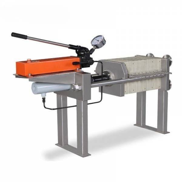
Description of filter press frame and hydraulics
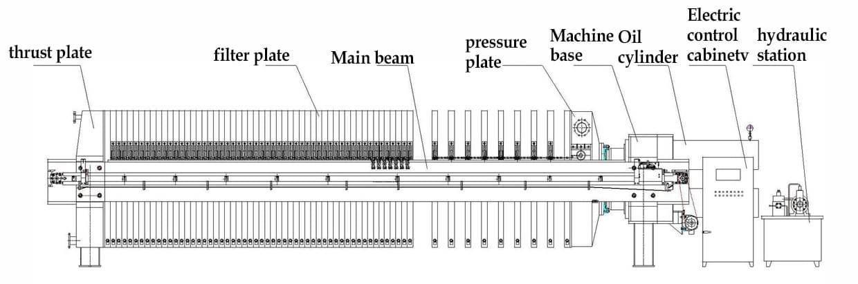
The HPL470 and HPL500 filter presses are "sidebar" filter presses with a manual hydraulic pump. They consist of a carbon steel frame with sidebars mounted on a skid. The follower, also known as the moveable head, has a moveable extension piece that allows it to be moved further out of the way during cake discharge. The extension piece has buttons on both ends to ensure proper alignment during the closing of the press with the follower and the hydraulic cylinder.
The HPL500 filter press has a manual hydraulic hand pump with a reservoir and hydraulic cylinder. The closing force is 400 bar (6000 psig). There is a valve on the hand pump that controls whether hydraulic fluid is going to the cylinder or returned to the reservoir. The press also has a locking ring on the cylinder to mechanically maintain proper press closure.
The HPL470 filter press also has a manual hydraulic hand pump with a reservoir and hydraulic cylinder. The closing force is 4000 psig. Similar to the HPL500, it has a valve on the hand pump to control the hydraulic fluid flow and a locking ring on the cylinder to maintain press closure.
Frontal piping and press operation
The frontal piping of the filter press consists of bolt-on headers with center feed and four corner filtrate outlets. For corner feed membrane, the center feed is ignored, and the upper right-hand filtrate port is used for feeding.
During press operation, the proper cake thickness is selected, and the head, intermediate, and tail plates are installed, alternating the filtrate drainage ports. The press should be operated within the following restrictions: maximum pressure of 225 psig and a low flow flux rate not exceeding 15 l/m2-hr.
Installation and operation of recessed chamber plates
The recessed chamber plates used in the HPL470 and HPL500 filter presses are standard center feed plates. They have barrel-neck type cloths that are held in place by cloth ties.
To install the plates, they should be placed in the press in the proper order. A maximum of 4 chambers (5 plates) can be installed. If necessary, additional spacer plates can be added behind the end plate if the hydraulic cylinder strokes out.
Description, installation, and operation of membrane plate stack
The membrane plate stack used in the HPL470 and HPL500 filter presses consists of a series of membrane plates and "recessed" plates. The plates are alternated: recessed - membrane - recessed - membrane, etc. The membrane plates have a PP welded membrane.
For corner feed membranes, the slurry is fed into the upper right-hand corner of the plates. The cloths are individual sheets held in place using a locking ring assembly in the corner feed ports. An adapter plate is used to adapt the 500 mm press porting to the 470 mm plate porting of the membrane plates.
For center feed membranes, the slurry is fed into the center feed port. The cloths are barrel-neck types, except for the tail plate, which is a drape over type. Cloth ties are used to hold the cloth in place. An adapter plate is also used to adapt the press porting to the plate porting of the membrane plates.
During installation, the plates should be placed in the press in the proper order, with a maximum of 4 chambers (5 plates) being installed. Additional spacer plates can be added behind the end plate if needed.
During the operation of the membrane press, the press is filled conventionally with a feed pressure of 100 psig max. The membranes can be inflated using compressed gas or water, with a maximum inflation pressure of 225 psig. Only every other membrane plate needs to be inflated, even if a "full" membrane plate stack is used.
It's important to note that there are two basic filter press configurations: recessed chamber and membrane. The HPL470 and HPL500 pilot presses are suitable for testing for both configurations. Recessed chamber tests require the filter press, feed pump(s), and a mixing tank with a mixer. Membrane tests require all the equipment needed for recessed chamber tests, as well as a source of compressed gas for membrane squeeze and the necessary equipment to control the membrane squeeze. The HPL300 is suitable for recessed chamber tests and basic membrane tests without cake washing.
If you are interested in this product you can browse our company website:https://kindle-tech.com/product-categories/heated-lab-press, we always insist on the principle of quality first. During the production process, we strictly control every step of the process, using high quality materials and advanced production technology to ensure the stability and durability of our products. to ensure that their performance meets the highest standards. We believe that only by providing customers with excellent quality can we win their trust and long-term cooperation.
Related Products
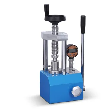
- Hydraulic Diaphragm Lab Filter Press for Laboratory Filtration
- Laboratory Hydraulic Pellet Press for XRF KBR FTIR Lab Applications
- Laboratory Hydraulic Press Split Electric Lab Pellet Press
- Manual Cold Isostatic Pressing Machine CIP Pellet Press
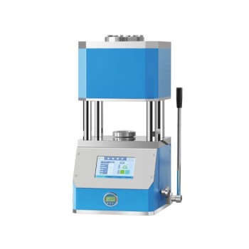
- Automatic High Temperature Heated Hydraulic Press Machine with Heated Plates for Lab