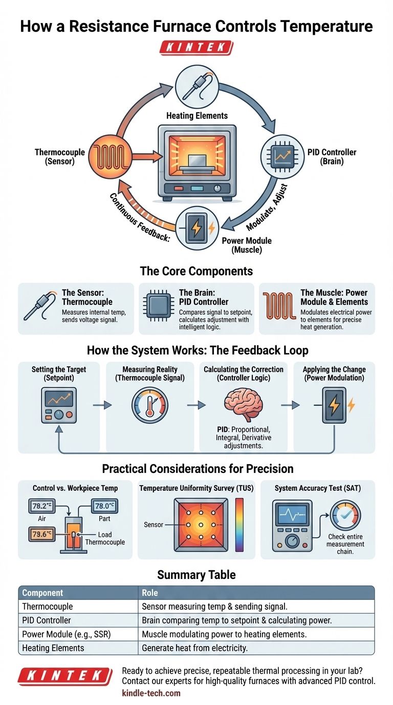
At its core, a resistance furnace controls temperature using a closed-loop feedback system. This system continuously measures the internal temperature with a sensor, compares it to the desired target temperature (the setpoint), and precisely adjusts the electrical power sent to the heating elements to correct any difference. The primary components that make this possible are a thermocouple, a temperature controller, and a power-regulating module.
The key takeaway is that furnace temperature control is not a static setting, but a dynamic, continuous process. It's an intelligent system designed to achieve and maintain a specific temperature by constantly measuring, comparing, and adjusting the energy input.
The Core Components of a Temperature Control System
To understand how control is achieved, you must first understand the function of each critical component. Think of it as a team where each member has a distinct and essential role.
The Sensor: The Thermocouple
A thermocouple is the system's nerve ending. It is a sensor made of two different metals joined at one end, which is placed inside the furnace chamber.
As the temperature changes, it produces a tiny, predictable voltage. This voltage signal is a direct electronic representation of the temperature at that specific point.
The Brain: The Temperature Controller
The temperature controller is the central processing unit of the system. It receives the voltage signal from the thermocouple and converts it into a temperature reading.
Its main job is to constantly compare this actual temperature to the setpoint you have programmed. Modern furnaces almost universally use a PID (Proportional-Integral-Derivative) controller, an intelligent algorithm that anticipates temperature changes to prevent overshooting or undershooting the target.
The Muscle: Heating Elements and the Power Module
The furnace's heating elements are the components that actually generate heat when electricity passes through them.
Based on the calculations from the PID controller, a power module (like a Solid-State Relay or SCR) modulates the amount of electricity flowing to these elements. If the furnace is too cool, the controller tells the module to send more power; if it's too hot, it reduces or cuts off the power.
How the System Works: The Feedback Loop in Action
These components work together in a continuous cycle, much like a modern thermostat controlling the climate in your home.
1. Setting the Target (Setpoint)
First, an operator uses a control panel or software interface to enter the desired temperature profile. This could be a single temperature to hold or a complex series of ramps and soaks over time.
2. Measuring Reality (Thermocouple Signal)
The thermocouple inside the furnace constantly measures the real-time temperature of the furnace atmosphere or a specific load and sends its signal to the controller.
3. Calculating the Correction (Controller Logic)
The controller instantly compares the thermocouple's reading to the setpoint. A simple "on/off" controller would just turn the heat on when it's too cold and off when it's too hot, leading to wide temperature swings.
A PID controller is far more sophisticated. It analyzes how far the temperature is from the setpoint (Proportional), how long it has been off-target (Integral), and how quickly it is changing (Derivative). This allows it to make nuanced adjustments, applying just the right amount of power to approach and hold the setpoint smoothly.
4. Applying the Change (Power Modulation)
The controller's decision is executed by the power module, which precisely increases or decreases the energy delivered to the heating elements. This constant cycle of measure-compare-adjust is what allows a furnace to maintain exceptionally stable temperatures.
Understanding the Trade-offs and Practical Considerations
Simply controlling the furnace temperature is not the whole story. For professional and industrial applications, accuracy and uniformity are what truly matter.
Control Temperature vs. Workpiece Temperature
The control thermocouple measures the temperature at one spot, which is typically the furnace atmosphere. However, the actual temperature of the material you are heating (the "workpiece" or "load") can lag behind.
For critical processes, a separate load thermocouple is placed in direct contact with or very near the workpiece to ensure it reaches the correct temperature, not just the air around it.
The Challenge of Temperature Uniformity
A single thermocouple only guarantees the temperature at its specific location. The temperature across the entire furnace chamber can vary, creating hot and cold spots.
This is why industrial furnaces undergo a Temperature Uniformity Survey (TUS), where multiple thermocouples are placed throughout the working volume to map out its thermal characteristics and ensure the entire zone meets specifications.
The Importance of System Accuracy
The entire control loop is only as good as its weakest link. A System Accuracy Test (SAT) is a calibration procedure that verifies the accuracy of the entire instrumentation chain, from the thermocouple tip to the temperature display on the controller. This ensures the temperature you set and see is the temperature you are actually getting.
How to Apply This to Your Project
Your specific goal will determine which aspects of temperature control are most critical for you.
- If your primary focus is process precision: You must use a PID controller and consider implementing load thermocouples to monitor the actual temperature of your parts.
- If your primary focus is quality assurance: Regular System Accuracy Tests (SAT) and Temperature Uniformity Surveys (TUS) are non-negotiable to validate your process.
- If your primary focus is general heating or non-critical work: A standard single-point control system is effective, but remain aware that the temperature of your workpiece may differ from the furnace's setpoint.
Understanding this control system empowers you to move beyond simply operating the furnace and begin truly controlling your thermal process for repeatable, high-quality results.
Summary Table:
| Component | Role in Temperature Control |
|---|---|
| Thermocouple | Sensor that measures the furnace temperature and sends a voltage signal. |
| PID Controller | The "brain" that compares actual temperature to the setpoint and calculates the needed power adjustment. |
| Power Module (e.g., SSR) | The "muscle" that modulates electrical power to the heating elements based on the controller's signal. |
| Heating Elements | Generate heat when electricity flows through them, directly heating the furnace chamber. |
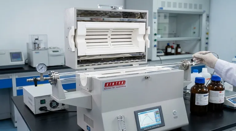
Ready to achieve precise, repeatable thermal processing in your lab?
KINTEK specializes in high-quality lab furnaces with advanced PID control systems, designed for accuracy and reliability. Whether your work requires general heating or critical process validation with TUS and SAT, our equipment ensures you have complete control over your thermal applications.
Contact our experts today to discuss your specific furnace needs and discover the right solution for your laboratory.
Visual Guide
Related Products
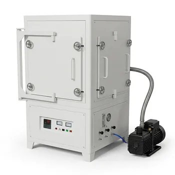
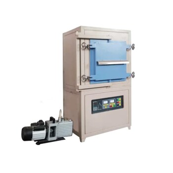
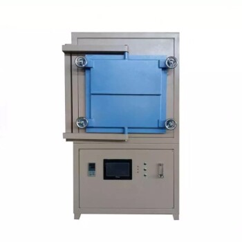
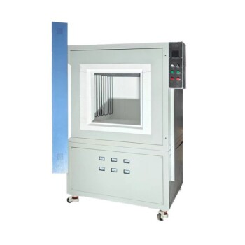
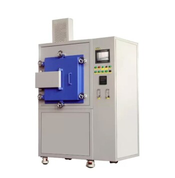
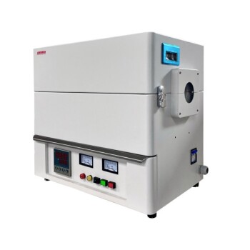
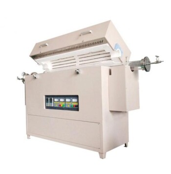
- 1200℃ Controlled Atmosphere Furnace Nitrogen Inert Atmosphere Furnace
- 1700℃ Controlled Atmosphere Furnace Nitrogen Inert Atmosphere Furnace
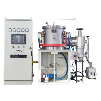
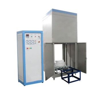
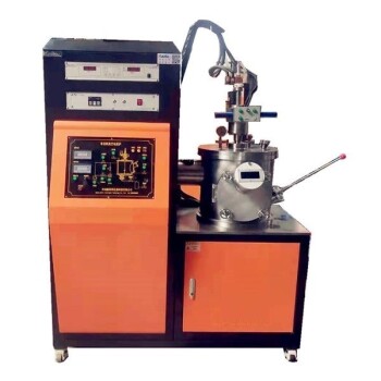
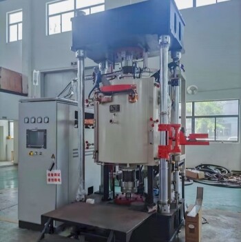
- 2200 ℃ Tungsten Vacuum Heat Treat and Sintering Furnace
- Vertical High Temperature Graphite Vacuum Graphitization Furnace
- Graphite Vacuum Furnace High Thermal Conductivity Film Graphitization Furnace
People Also Ask
- Can you braze copper to brass without flux? Yes, but only under these specific conditions.
- What is a controlled atmosphere furnace? Achieve Purity and Precision in High-Temp Processing
- What are the two primary purposes of using a controlled atmosphere? Master Protection vs. Material Modification
- What is the function of a high-precision controlled atmosphere furnace for Alloy 617? Simulate Extreme VHTR Conditions
- What is the necessity of a controlled atmosphere furnace for corrosion research? Replicating Realistic Industrial Risks