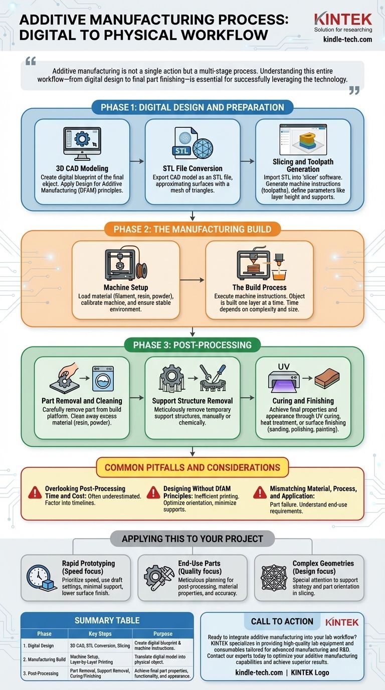
To be clear, the additive manufacturing (AM) process is a comprehensive digital-to-physical workflow that extends far beyond the printing stage itself. It begins with a digital concept and progresses through several critical steps: creating a 3D model, converting and slicing that model for the machine, the physical build process, and a final series of post-processing and finishing steps to produce the final part.
Additive manufacturing is not a single action but a multi-stage process. Understanding this entire workflow—from digital design to final part finishing—is essential for successfully leveraging the technology and avoiding costly downstream problems.
Phase 1: Digital Design and Preparation
Before any material is used, the foundation of the part is built in a purely digital environment. This preparatory phase is arguably the most critical, as decisions made here dictate the success of the entire process.
3D CAD Modeling
The process begins with a 3D model created in Computer-Aided Design (CAD) software. This is the digital blueprint of the final object.
Engineers and designers build the part's geometry, ensuring it meets all functional and structural requirements. This is also the stage where principles of Design for Additive Manufacturing (DFAM) are applied to optimize the part for the printing process.
STL File Conversion
The universal language for most 3D printers is the STL (stereolithography) file format. The completed CAD model is exported as an STL file.
This format approximates the surfaces of the model using a mesh of triangles. The resolution of this mesh is a key parameter that can affect the surface quality of the final print.
Slicing and Toolpath Generation
The STL file is then imported into a "slicer" software. This program digitally cuts the 3D model into hundreds or thousands of thin, horizontal layers.
For each layer, the software generates the precise machine instructions, or toolpaths, that the printer will follow. This is also where critical print parameters like layer height, print speed, and support structure placement are defined.
Phase 2: The Manufacturing Build
This is the phase where the digital blueprint is translated into a physical object, layer by painstaking layer.
Machine Setup
Proper machine setup is non-negotiable. This involves loading the selected material, whether it's a polymer filament, a vat of liquid resin, or a bed of metal powder.
The operator also performs critical calibrations, cleans the build platform, and ensures the machine's environment (e.g., temperature) is stable and correct for the material being used.
The Build Process
The printer executes the instructions from the sliced file, building the object one layer at a time. The specific technology—such as FDM, SLA, or SLS—dictates exactly how each layer is formed and bonded to the previous one.
This process is often automated and can take anywhere from a few hours to several days, depending on the part's size, complexity, and the chosen technology.
Phase 3: Post-Processing
A common misconception is that a part is finished the moment the printer stops. In reality, significant post-processing is almost always required to turn a raw print into a functional, finished component.
Part Removal and Cleaning
Once the build is complete, the part must be carefully removed from the build platform. Depending on the technology, this is followed by a cleaning process.
This could involve washing away excess liquid resin, blowing or brushing off unused powder, or simply detaching the part from a build plate.
Support Structure Removal
Complex geometries with overhangs require temporary support structures to be printed alongside the part. These supports must be meticulously removed.
This can be a manual process using hand tools, or it may involve dissolving the supports in a chemical solution. It is often the most labor-intensive part of the entire workflow.
Curing and Finishing
Many raw parts require additional steps to achieve their final material properties and desired appearance. This can include UV curing for resins to maximize strength, heat treatment for metals, or surface finishing techniques like sanding, polishing, or painting.
Common Pitfalls and Considerations
Successfully navigating the AM workflow requires an awareness of its unique challenges. Overlooking these can lead to failed prints, wasted resources, and parts that do not meet specifications.
Overlooking Post-Processing Time and Cost
Teams often underestimate the labor and time required for post-processing, especially support removal and surface finishing. This must be factored into project timelines and cost analyses from the very beginning.
Designing Without DfAM Principles
A part designed for traditional manufacturing will rarely print efficiently or effectively. Successful AM relies on applying DfAM principles, such as optimizing part orientation, minimizing the need for supports, and consolidating assemblies into single parts.
Mismatching Material, Process, and Application
Not all AM technologies are suitable for every application. Choosing the wrong material or printing process can result in a part that fails to meet thermal, chemical, or mechanical requirements. A deep understanding of the end-use application is critical.
Applying This to Your Project
Your approach to the AM workflow should be dictated by your end goal.
- If your primary focus is rapid prototyping: You can prioritize speed by using draft-quality print settings, designing for minimal support, and accepting a lower-quality surface finish.
- If your primary focus is producing end-use parts: Meticulous planning for post-processing, material properties, and dimensional accuracy is non-negotiable from the initial design stage.
- If your primary focus is complex geometries: Pay special attention to support strategy and part orientation in the slicing stage to ensure a successful build and simplify post-processing.
Ultimately, viewing additive manufacturing as an integrated, end-to-end process is the key to unlocking its full potential.
Summary Table:
| Phase | Key Steps | Purpose |
|---|---|---|
| 1. Digital Design | 3D CAD Modeling, STL Conversion, Slicing | Create a digital blueprint and prepare machine instructions. |
| 2. Manufacturing Build | Machine Setup, Layer-by-Layer Printing | Translate the digital model into a physical object. |
| 3. Post-Processing | Part Removal, Support Removal, Curing/Finishing | Achieve final part properties, functionality, and appearance. |
Ready to integrate additive manufacturing into your lab workflow? KINTEK specializes in providing high-quality lab equipment and consumables tailored for advanced manufacturing and R&D. Whether you are prototyping new designs or producing end-use parts, our expertise ensures you have the right tools for every step of the AM process—from digital design to final finishing. Contact our experts today to optimize your additive manufacturing capabilities and achieve superior results.
Visual Guide