In magnetron sputtering, the mean free path is not a fixed number but a critical operating parameter that is deliberately made long, typically on the order of several centimeters. This is achieved by operating at very low pressures (around 0.1 Pa). The entire purpose of the magnetic field in a magnetron is to make the plasma efficient enough to be sustained at these low pressures, which in turn maximizes the mean free path for sputtered atoms.
The core principle of magnetron sputtering is to create a low-pressure environment, resulting in a long mean free path. This allows sputtered atoms to travel from the target to the substrate with minimal energy loss from gas collisions, which is the direct cause of the high-quality, dense, and pure films the technique is known for.
The Role of Mean Free Path in Sputtering
To understand why magnetron sputtering is so effective, we must first understand the concept of mean free path and its impact on the coating process.
Defining Mean Free Path
The mean free path (MFP) is the average distance a particle—in this case, a sputtered atom or an ion—travels before it collides with another particle.
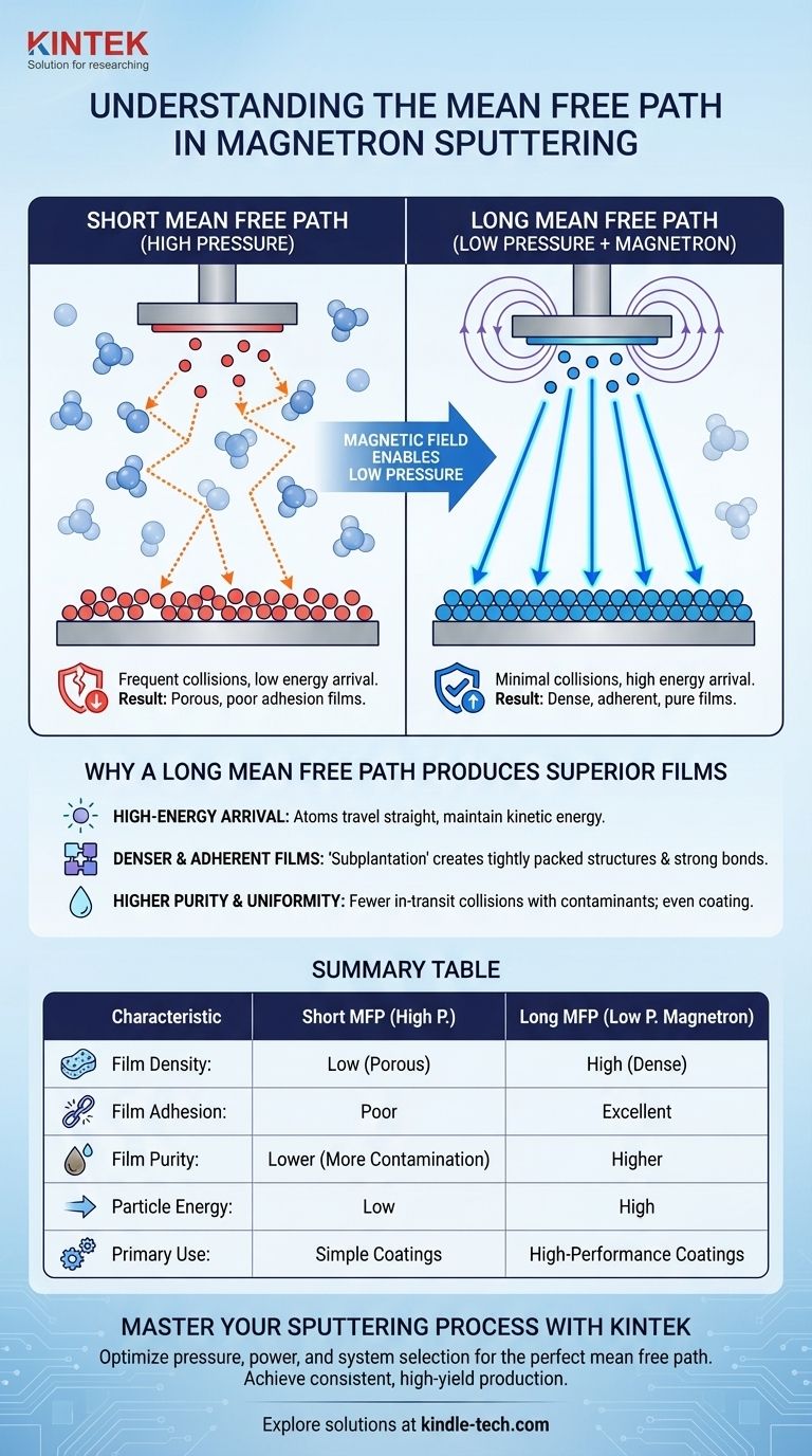
This distance is inversely proportional to the pressure inside the vacuum chamber. High pressure means more gas atoms are present, leading to a very short mean free path. Conversely, low pressure means fewer gas atoms, resulting in a long mean free path.
The Problem with a Short Mean Free Path
In older, simpler sputtering techniques that required higher pressures, the mean free path was short. Sputtered atoms would leave the target material but quickly collide with atoms of the background argon gas.
Each collision would cause the sputtered atom to lose kinetic energy and change its direction. By the time it reached the substrate, it was a low-energy particle that would gently land on the surface, creating films that were often porous and had poor adhesion.
The Magnetron Solution for a Long Mean Free Path
Magnetron sputtering introduces a strong magnetic field near the target material. This field traps electrons, forcing them into a spiral path and dramatically increasing their chances of colliding with and ionizing the argon gas atoms.
This enhanced ionization efficiency allows a stable plasma to be maintained at much lower pressures. This low-pressure environment is the key, as it directly creates the long mean free path needed for high-quality deposition.
How a Long Mean Free Path Produces Superior Films
The advantages of magnetron sputtering described in industry literature are a direct consequence of operating in this long mean free path regime.
High-Energy Particle Arrival
With a long mean free path, sputtered atoms travel from the target to the substrate in a near straight line, experiencing few or no energy-robbing collisions.
They arrive at the substrate with almost all of their initial high kinetic energy. This is a fundamental difference from high-pressure processes.
Denser and More Adherent Films
High-energy atoms don't just land on the surface; they embed themselves slightly, a process called subplantation. This impact dislodges loosely-bonded atoms and forces them into a more tightly packed, dense film structure.
This energetic bombardment is also why magnetron-sputtered films exhibit extremely high adhesion to the substrate. The atoms effectively form a strong, intermixed bond at the interface.
Higher Purity and Uniformity
A long mean free path means sputtered atoms are less likely to collide with and react to residual gas impurities in the chamber. This results in films with very low impurity levels.
Furthermore, the line-of-sight trajectory of the high-energy atoms contributes to creating uniform and even coatings across large areas, a critical factor for industrial production.
Understanding the Trade-offs
While creating a long mean free path environment is highly beneficial, it introduces complexity. The primary trade-off is the equipment itself.
Increased System Complexity
Achieving this low-pressure, magnetically-confined plasma requires more sophisticated hardware. The inclusion of powerful magnets and the power supplies to run the system make a magnetron setup more complex and costly than a simple high-pressure diode sputtering system.
The Goal Dictates the Method
This complexity is a necessary trade-off. For applications demanding high performance—such as dense optical coatings, durable wear-resistant layers, or high-purity electronic films—the quality imparted by the long mean free path process is non-negotiable.
Making the Right Choice for Your Goal
Understanding the physics allows you to connect your desired film properties back to the process parameters. The "mean free path" is your conceptual tool for this.
- If your primary focus is film density and adhesion: You need sputtered atoms to arrive with maximum energy, which requires the long mean free path created by a low-pressure magnetron process.
- If your primary focus is film purity: You must minimize in-transit collisions with contaminants, which is another direct benefit of the long mean free path.
- If your primary focus is throughput and uniformity for industrial scale: The high deposition rates and scalability of magnetron sputtering are enabled by the efficiency of its magnetically-confined, low-pressure plasma.
Ultimately, the magnetron is a tool specifically engineered to lengthen the mean free path, because that is the fundamental mechanism for producing superior thin films.
Summary Table:
| Characteristic | Short Mean Free Path (High Pressure) | Long Mean Free Path (Low Pressure, Magnetron) |
|---|---|---|
| Film Density | Low (porous) | High (dense) |
| Film Adhesion | Poor | Excellent |
| Film Purity | Lower (more contamination) | Higher |
| Particle Energy at Substrate | Low (due to collisions) | High (direct trajectory) |
| Primary Use Case | Simpler, less demanding coatings | High-performance optical, electronic, wear-resistant coatings |
Ready to achieve superior thin film results?
The principles of magnetron sputtering are key to producing the high-quality, dense, and pure films your R&D or production demands. At KINTEK, we specialize in providing the advanced lab equipment and consumables needed to master this process.
Our expertise in vacuum and coating technologies can help you:
- Select the right magnetron sputtering system for your specific material and application goals.
- Optimize process parameters like pressure and power to perfectly control the mean free path.
- Ensure consistent, high-yield production of reliable thin films.
Let's discuss how we can support your laboratory's success. Contact our experts today for a personalized consultation!
Visual Guide
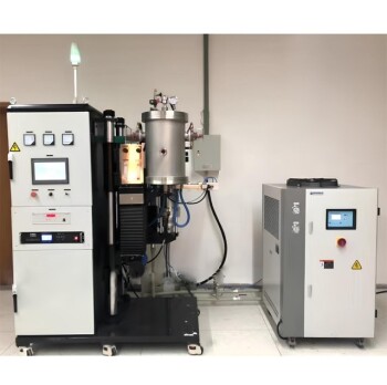
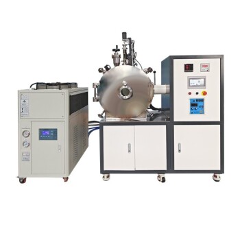
Related Products
- Microwave Plasma Chemical Vapor Deposition MPCVD Machine System Reactor for Lab and Diamond Growth
- Vacuum Heat Treat and Molybdenum Wire Sintering Furnace for Vacuum Sintering
- Vacuum Arc Induction Melting Furnace
- Molybdenum Tungsten Tantalum Special Shape Evaporation Boat
- Reference Electrode Calomel Silver Chloride Mercury Sulfate for Laboratory Use
People Also Ask
- How do vacuum pumps and valves collaborate in MPCVD? Achieve Precise Pressure Control for Superior CNT Synthesis
- How does MPCVD work? A Guide to Low-Temperature, High-Quality Film Deposition
- How are CVD diamonds created? Discover the Science of Lab-Grown Diamond Precision
- How does a microwave plasma reactor facilitate the synthesis of diamond? Master MPCVD with Precision Technology
- What are the advantages of a Microwave Plasma CVD reactor for MCD/NCD coatings? Precision Multilayer Diamond Engineering