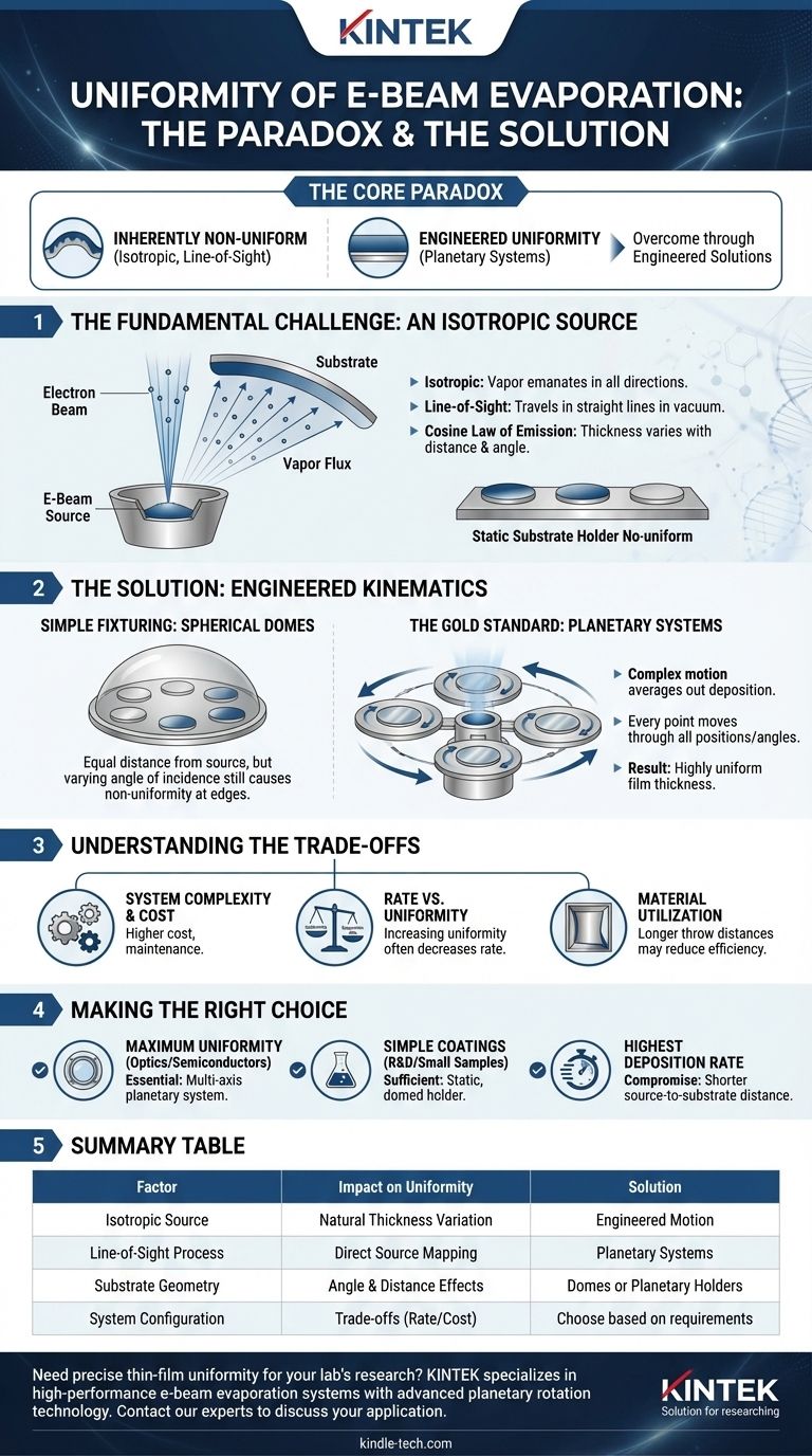
At its core, the uniformity of e-beam evaporation presents a paradox. The fundamental physics of the process creates an inherently non-uniform coating, yet with proper system design, it is capable of producing films with excellent uniformity. The natural tendency is for material to deposit more thickly on surfaces directly above the evaporation source and thinly on surfaces at an angle.
The central challenge of e-beam evaporation is that it is an isotropic, line-of-sight process, much like a bare lightbulb illuminating a room. However, this challenge is overcome through engineered solutions—specifically planetary rotation systems—that average out the deposition to achieve high uniformity.
The Fundamental Challenge: An Isotropic Source
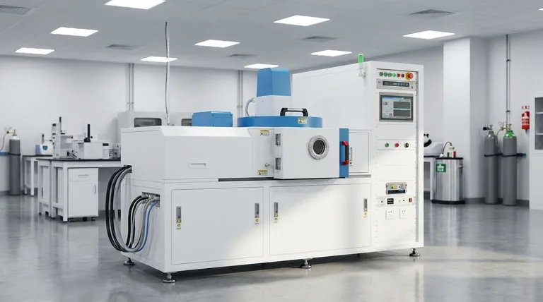
Electron-beam evaporation is a Physical Vapor Deposition (PVD) technique where a high-energy electron beam heats a source material in a crucible, causing it to evaporate. This vapor then travels through a vacuum and condenses on a cooler substrate, forming a thin film.
What "Isotropic" Means for Deposition
The evaporation process is isotropic, meaning the vaporized atoms emanate from the source in all directions. Imagine the source as a point emitting particles in a wide cone.
This creates a natural variation in film thickness. A substrate placed directly over the source receives the highest flux of material, while a substrate off to the side receives significantly less.
The Impact of Source-to-Substrate Geometry
The deposition rate at any point on a substrate is governed by the distance from the source and the angle of incidence. This is often described by the cosine law of emission.
Substrates or parts of a substrate that are farther away or at a steeper angle to the source will inherently receive a thinner coating. This is the primary reason why simple, static substrate holders result in poor uniformity over large areas.
A "Line-of-Sight" Process
E-beam evaporation operates in a high vacuum, which means the evaporated atoms travel in a straight line until they hit a surface. There is very little gas scattering to randomize their direction.
This "line-of-sight" characteristic is beneficial for creating dense films and for a technique called lift-off patterning, but it compounds the uniformity problem. Any variation in the source emission is directly mapped onto the substrates.
The Solution: Engineered Kinematics
To solve the inherent non-uniformity, system designers do not change the physics of evaporation; they change the position of the substrates during the process.
Simple Fixturing: Spherical Domes
A basic method to improve uniformity is to mount substrates on a spherical dome or "calotte." This ensures that every substrate is at an equal distance from the source material.
While this helps, it does not solve the problem of the angle of incidence. Substrates at the edge of the dome are still at a sharper angle to the vapor flux and will be coated more thinly than those in the center.
The Gold Standard: Planetary Systems
The most effective solution is a planetary substrate holder. In this setup, individual wafers or substrates are mounted on smaller rotating plates (the "planets"). These planets, in turn, revolve around the central evaporation source (the "sun").
This complex motion ensures that every point on every substrate is systematically moved through all possible positions and angles relative to the source. The high-deposition-rate zones and low-deposition-rate zones are averaged out over the entire surface. The result is a highly uniform film thickness across one or many substrates.
Understanding the Trade-offs
Achieving high uniformity with e-beam evaporation is not without its costs and considerations. It is an engineering solution with direct consequences.
System Complexity and Cost
Planetary systems involve complex mechanical components, including gears and rotary feedthroughs, that must operate flawlessly in a high-vacuum environment. This adds significant cost, complexity, and maintenance requirements to the deposition system.
Rate vs. Uniformity
For a given planetary system, uniformity can often be further improved by increasing the distance between the source and the substrates. However, this also decreases the deposition rate, as fewer atoms per second will reach the substrates. This trade-off between throughput and uniformity is a critical process parameter.
Material Utilization
While e-beam evaporation is generally efficient, optimizing for uniformity with long throw distances can reduce overall material utilization, as more of the evaporated material coats the chamber walls instead of the substrates.
Making the Right Choice for Your Goal
Your uniformity requirement is the single most important factor in determining the necessary system configuration.
- If your primary focus is maximum uniformity for demanding optics or semiconductors: A system with a multi-axis planetary substrate holder is essential to average out deposition variations.
- If your primary focus is simple coatings on small samples or R&D: A static, domed holder may be a sufficient and far more cost-effective solution for your needs.
- If your primary focus is the highest possible deposition rate: You must accept a compromise on uniformity, which can be achieved by using a shorter source-to-substrate distance.
Ultimately, understanding that uniformity in e-beam evaporation is an engineered property, not an inherent one, empowers you to select the right tool for your specific objective.
Summary Table:
| Factor | Impact on Uniformity | Solution |
|---|---|---|
| Isotropic Source | Creates natural thickness variation | Engineered substrate motion |
| Line-of-Sight Process | Maps source variation directly to substrate | Planetary rotation systems |
| Substrate Geometry | Angle & distance from source affect thickness | Spherical domes or planetary holders |
| System Configuration | Trade-off between rate, uniformity, and cost | Choose based on application requirements |
Need to achieve precise thin-film uniformity for your lab's optics or semiconductor research? KINTEK specializes in high-performance lab equipment, including e-beam evaporation systems with advanced planetary rotation technology. Our solutions are designed to help you overcome inherent deposition challenges and achieve the exacting uniformity your work demands. Contact our experts today to discuss your specific application and find the right system for your goals.
Visual Guide
Related Products
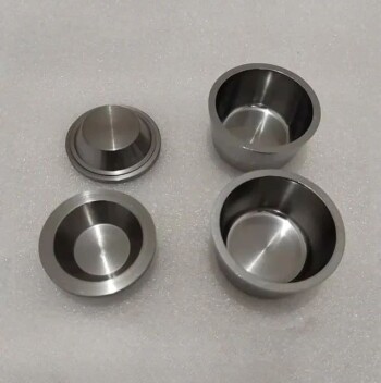
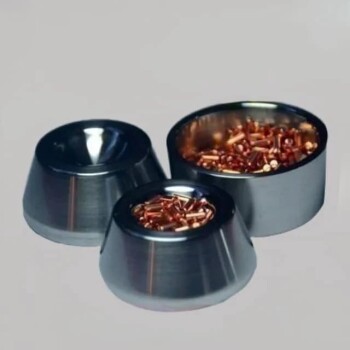
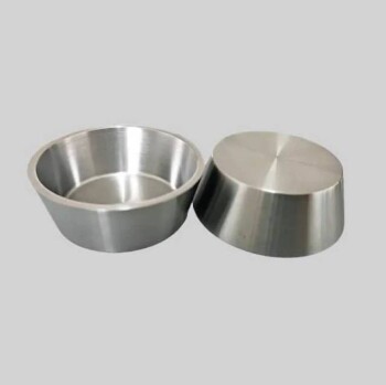
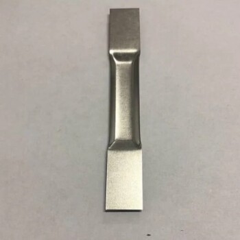
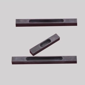
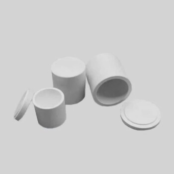
- Electron Beam Evaporation Coating Oxygen-Free Copper Crucible and Evaporation Boat
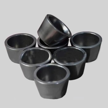
- Electron Beam Evaporation Coating Tungsten Crucible and Molybdenum Crucible for High Temperature Applications
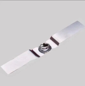
- Electron Beam Evaporation Coating Gold Plating Tungsten Molybdenum Crucible for Evaporation
- E Beam Crucibles Electron Gun Beam Crucible for Evaporation
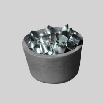
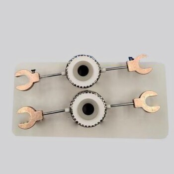
- Electron Beam Evaporation Coating Conductive Boron Nitride Crucible BN Crucible
People Also Ask
- What is e-beam evaporation? Achieve High-Purity Thin Film Deposition for Your Lab
- How is an electron beam evaporator cooled during deposition? Essential Thermal Management for Stable Processes
- What is the deposition rate of e-beam evaporation? Control Thin Film Quality and Speed
- What is e-beam evaporation used for? Precision Coating for Optics, Aerospace & Electronics
- What are the applications of e-beam evaporation? Achieve High-Purity Coatings for Optics & Electronics