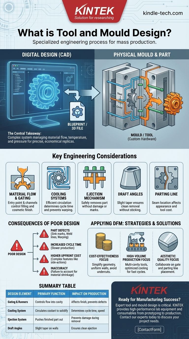
In short, tool and mould design is the specialized engineering process of creating the manufacturing hardware—the "mould" or "tool"—used to produce parts in high volumes. It is the critical bridge that translates a digital product design into a repeatable, physical object by shaping raw materials like molten plastic or metal under pressure. The quality of this design dictates the final part's accuracy, finish, and cost.
The central takeaway is that effective tool and mould design is far more than simply creating a negative impression of a part. It is a complex system that must expertly manage material flow, temperature, and pressure to ensure that every part produced is a precise and economical replica of the original design.
The Core Function: From Blueprint to Physical Part
A product may look perfect in a CAD file, but it is the tool and mould design that determines if it can be manufactured successfully. This process transforms a digital concept into a tangible, mass-produced reality.
Defining the "Mould" or "Tool"
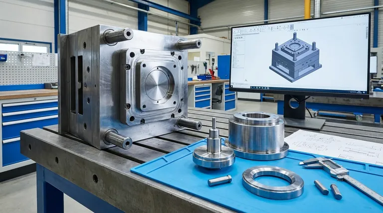
The mould (often called the tool or die) is typically a block of high-strength steel or aluminum that has been precisely machined. It contains a cavity that is the negative shape of the part you intend to create.
This tool is the heart of processes like injection moulding, where molten plastic is forced into the cavity, cooled, and then ejected as a finished part. The terms "tool" and "mould" are often used interchangeably to refer to this entire custom-built assembly.
It's More Than Just a Cavity
A simple cavity is not enough. The design must incorporate a series of complex mechanical systems that work in perfect harmony. These systems are responsible for getting the material in, shaping it correctly, cooling it efficiently, and getting the finished part out without damage.
Key Engineering Considerations in Mould Design
The success of a manufactured part is determined by a handful of critical design principles that must be addressed long before any metal is cut.
Material Flow and Gating
The gate is the entry point where molten plastic flows into the mould cavity, and the runners are the channels that lead to it. The size, shape, and location of the gate are critical for ensuring the cavity fills evenly and for controlling the cosmetic appearance of the final part.
Cooling Systems
Channels are drilled throughout the mould to circulate a coolant (usually water). An efficient cooling system is paramount because it dictates the cycle time—the total time it takes to produce one part. Uneven or slow cooling is a primary cause of part defects like warping.
Ejection Mechanism
Once the part has cooled and solidified, it must be pushed out of the mould. This is accomplished by an ejection system, which uses ejector pins to apply force to the part. The placement and size of these pins must be carefully calculated to avoid leaving marks or deforming the product.
Draft Angles
For a part to be removed cleanly from the mould, its walls cannot be perfectly vertical. A slight taper, known as a draft angle, is required. Without adequate draft, the part will scrape against the mould wall during ejection, causing cosmetic damage or causing it to get stuck.
Parting Line
The parting line is the seam where the two halves of the mould meet. Its location is a critical design decision that affects the part's final appearance and can influence the complexity and cost of the tool itself.
Understanding the Consequences of Poor Design
Flaws in tool and mould design are not easily fixed and have significant consequences for both quality and cost.
The Impact on Part Quality
Poor design is the direct cause of common manufacturing defects. Sink marks (depressions on the surface), weld lines (where two plastic flows meet), and warping are all symptoms of a mould that fails to properly manage material flow and temperature.
The Link to Production Speed
A poorly designed cooling or ejection system dramatically increases cycle time. Even a few extra seconds per part can translate into thousands of dollars in lost production efficiency over the lifetime of a product.
The Upfront Cost of Complexity
Features like undercuts or threads require complex mechanisms like side-actions or lifters to be built into the mould. While necessary for some designs, these features significantly increase the cost, complexity, and maintenance requirements of the tool.
Accounting for Material Shrinkage
Every plastic has a unique shrinkage rate—it shrinks as it cools. The mould designer must calculate this rate precisely and make the mould cavity slightly larger than the final part dimensions to compensate. Failure to do so results in parts that are out of tolerance.
Applying This to Your Project
The principles of tool and mould design are directly linked to the practice of Design for Manufacturability (DFM). Thinking about how the part will be moulded from the very beginning is essential.
- If your primary focus is cost-effectiveness: Simplify your part geometry, design uniform wall thicknesses, and avoid complex features like undercuts to reduce tool cost.
- If your primary focus is high-volume production: Invest in a durable multi-cavity steel tool with a highly optimized cooling system to achieve the lowest possible cycle time.
- If your primary focus is aesthetic quality: Collaborate closely with the mould designer on the placement of gates and the parting line to minimize their visual impact.
Ultimately, investing in expert tool and mould design is a direct investment in the quality, consistency, and profitability of your final product.
Summary Table:
| Design Element | Primary Function | Impact on Production |
|---|---|---|
| Gating & Runners | Controls the flow of molten material into the cavity. | Affects part finish and prevents defects like weld lines. |
| Cooling System | Circulates coolant to solidify the part. | Directly determines cycle time and production speed. |
| Ejection System | Pushes the finished part out of the mould. | Prevents damage to the part during removal. |
| Draft Angles | A slight taper on vertical walls. | Ensures the part can be ejected cleanly without sticking. |
Ready to turn your product design into a manufacturing success?
Expert tool and mould design is critical for achieving part accuracy, cosmetic quality, and cost-effective production cycles. At KINTEK, we specialize in providing the high-performance lab equipment and consumables that support the entire manufacturing process, from prototyping to high-volume production.
Our target customers in R&D and manufacturing rely on our solutions to ensure their tools operate at peak efficiency. Let us help you optimize your production.
Contact our experts today to discuss your project needs.
Visual Guide
Related Products
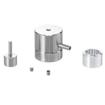
- Cylindrical Press Mold for Lab Applications
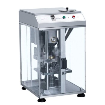
- Single Punch Electric Tablet Press Machine Laboratory Powder Tablet Punching TDP Tablet Press
- Warm Isostatic Press for Solid State Battery Research
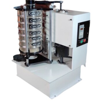
- Laboratory Vibratory Sieve Shaker Machine Slap Vibrating Sieve
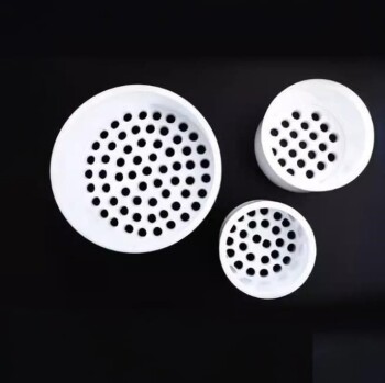
- Custom PTFE Teflon Parts Manufacturer for PTFE Mesh F4 Sieve
People Also Ask
- How does sample size affect analysis? Maximize the Reliability of Your Research
- Is it fitting the mould or mold? A Guide to Correct Spelling by Region
- What is the impact factor of powder metallurgy progress? A 2022 Analysis & Context
- What are the precautions to be taken while sampling? Ensure Data Accuracy and Minimize Bias
- What is a pellet die? A Guide to Creating Uniform Solid Samples from Powder