The primary motivation for utilizing a customized electrochemical flow cell over a traditional H-type cell is to overcome severe mass transfer limitations. While H-type cells rely on dissolving carbon dioxide into a liquid electrolyte, flow cells construct a compact gas/solid/liquid tri-phase interface. This design enables direct contact between the gas and the catalyst, bypassing solubility limits and allowing for industrial-grade current densities up to 400 mA cm⁻².
The Core Takeaway Traditional H-type cells are restricted by the low solubility of carbon dioxide in liquids, which acts as a bottleneck for reaction rates. Flow cells remove this barrier by delivering gas directly to the catalyst surface, making them the essential choice for testing high-performance, commercially relevant applications.
The Physical Limitations of H-Type Cells
To understand the necessity of flow cells, one must first understand the bottleneck inherent in the traditional design.
The Solubility Trap
H-type cells typically rely on bubbling carbon dioxide through an electrolyte to achieve saturation.
Because carbon dioxide has low solubility in aqueous solutions, the amount of fuel available to the catalyst is strictly limited.
Restricted Mass Transfer
In an H-cell, the reactant must diffuse through the liquid to reach the electrode surface.
At high reaction rates, the catalyst consumes carbon dioxide faster than it can diffuse through the liquid. This "starvation" prevents the system from reaching high current densities.
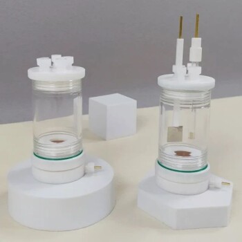
The Flow Cell Advantage
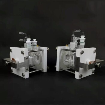
The customized flow cell is designed specifically to engineer around the diffusion barrier.
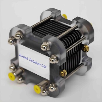
The Tri-Phase Interface
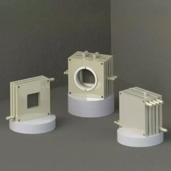
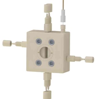
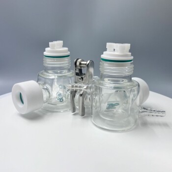
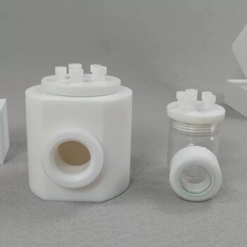
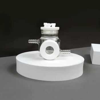
The critical innovation in a flow cell is the construction of a gas/solid/liquid interface.
Instead of waiting for gas to dissolve in liquid, the design brings the carbon dioxide gas, the solid catalyst, and the liquid electrolyte into simultaneous, direct contact.
Industrial-Grade Performance
By eliminating the diffusion path, the flow cell ensures the catalyst is constantly supplied with reactant.
This allows the system to operate at current densities of up to 400 mA cm⁻², a range necessary for industrial scaling that H-type cells simply cannot support.
Understanding the Trade-offs
While flow cells are superior for performance testing, H-type cells still hold value for specific analytical needs. It is important to choose the right tool for the specific metric you are measuring.
When to Use H-Type Cells
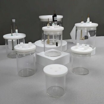
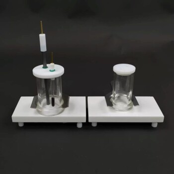
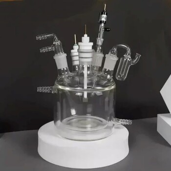
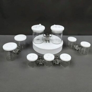
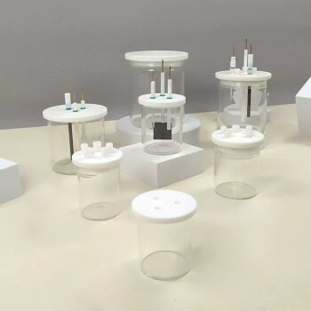
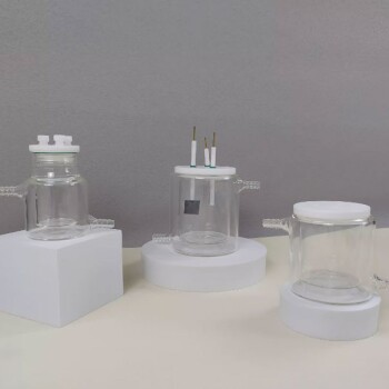
H-type cells utilize a proton exchange membrane and high-airtightness chambers to separate the anode and cathode.
This prevents reduction products (like alcohols) from migrating to the anode and being re-oxidized. Consequently, H-type cells remain highly effective for precise quantitative analysis of product selectivity and Faradaic efficiency in fundamental, low-current studies.
The Cost of Performance
The flow cell favors raw rate and throughput over the isolated precision of the H-cell.
Moving to a flow cell introduces complexity in system design but is a non-negotiable step when moving from fundamental mechanism studies to practical application testing.
Making the Right Choice for Your Goal
Select your cell architecture based on the specific maturity and goals of your research project:
- If your primary focus is Industrial Viability: Use a Flow Cell to demonstrate that your catalyst can sustain high current densities (e.g., 400 mA cm⁻²) without suffering from mass transfer limitations.
- If your primary focus is Intrinsic Selectivity: Use an H-Type Cell to accurately calculate Faradaic efficiency and product ratios in a stable, closed environment where product crossover is minimized.
Ultimately, use the H-cell to understand what the catalyst makes, and the flow cell to prove how fast it can make it.
Summary Table:
| Feature | H-Type Cell | Electrochemical Flow Cell |
|---|---|---|
| Interface Type | Liquid/Solid (Dissolved Gas) | Gas/Solid/Liquid (Tri-phase) |
| Mass Transfer | Limited by CO2 Solubility | High (Direct Gas Delivery) |
| Current Density | Low (< 50 mA cm⁻²) | Industrial-Grade (Up to 400 mA cm⁻²) |
| Primary Use | Fundamental Selectivity & FE Analysis | Industrial Viability & Rate Testing |
| Product Crossover | Minimal (Membrane Separated) | Higher Complexity in Management |
Accelerate your electrochemical research with KINTEK’s advanced laboratory solutions. Whether you are conducting fundamental studies or scaling for industrial viability, KINTEK provides high-performance electrolytic cells and electrodes, customized flow cells, and essential consumables like PTFE and ceramics. Our comprehensive portfolio, ranging from high-temperature reactors to battery research tools, ensures your lab is equipped for precision and speed. Contact our experts today to find the perfect cell architecture for your eCO2RR applications!
References
- Ting Xu, Shun Wang. Microenvironment engineering by targeted delivery of Ag nanoparticles for boosting electrocatalytic CO2 reduction reaction. DOI: 10.1038/s41467-025-56039-x
This article is also based on technical information from Kintek Solution Knowledge Base .
Related Products
- Electrolytic Electrochemical Cell Gas Diffusion Liquid Flow Reaction Cell
- Customizable CO2 Reduction Flow Cell for NRR ORR and CO2RR Research
- Electrolytic Electrochemical Cell with Five-Port
- Electrolytic Electrochemical Cell for Coating Evaluation
- PTFE Electrolytic Cell Electrochemical Cell Corrosion-Resistant Sealed and Non-Sealed
People Also Ask
- What are the three essential components that comprise an electrolytic cell? Key Elements of Chemical Synthesis
- What is galvanic cell or electrolytic cell? Unlock the Secrets of Electrochemical Power
- What role does an electrolytic cell play in the preparation of Cu-Bi protective coatings? Enhancing Material Durability
- How does the design of an electrochemical electrolytic cell influence the coating uniformity? Optimize Your Catalysts
- What is the correct shutdown and disassembly procedure after an experiment? Ensure Safety and Protect Your Equipment