In electrochemistry, we obsess over the purity of the electrolyte. We meticulously polish the working electrode. We calibrate the potentiostat to the millivolt.
Yet, we often ignore the one component that holds the entire chaos together: The lid.
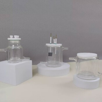
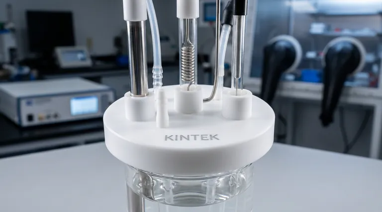
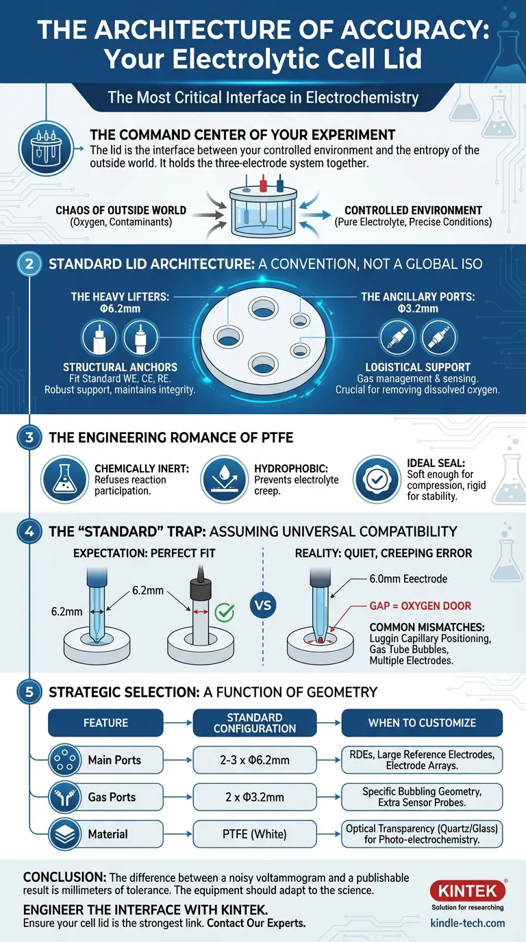
It seems like a trivial piece of plastic. In reality, the electrolytic cell lid is the interface between your controlled environment and the entropy of the outside world. It is the command center of the three-electrode system.
If the lid fails—if the apertures are loose, if the seal is compromised, or if the layout forces an awkward geometry—the experiment fails. Not with a bang, but with the quiet, creeping error of oxygen contamination or IR drop.
Here is the engineering logic behind the standard lid, and why relying on "standard" is often a dangerous assumption.
The Myth of the Universal Standard
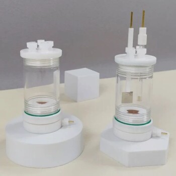
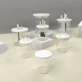
If you ask a supplier for a "standard" multifunctional electrolytic cell lid, you will likely receive a disc of PTFE (Teflon) drilled with specific coordinates.
There is no global ISO standard for this. However, convention has coalesced around two specific dimensions designed to accommodate the classic three-electrode setup.
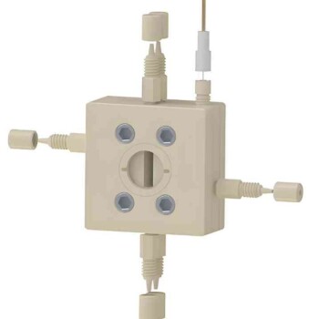
The Heavy Lifters: Φ6.2mm
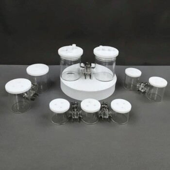
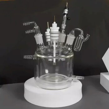
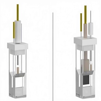
You will typically find two or three ports of this size. They are the structural anchors of the experiment.
- Purpose: To house the electrode bodies.
- Fit: Standard Working Electrodes (WE), Counter Electrodes (CE), and Reference Electrodes (RE).
- Why 6mm? This diameter is robust enough to support the electrode shaft without bending, yet small enough to maintain structural integrity of the lid.
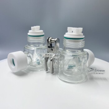
The Ancillary Ports: Φ3.2mm
These are the logistical support. A standard lid usually features two of these.
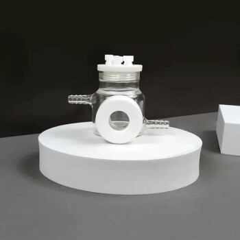
- Purpose: Gas management and sensing.
- Fit: Gas inlet/outlet tubes (for purging nitrogen or argon) or Luggin capillaries.
- Why it matters: Without these, you cannot remove dissolved oxygen, rendering reduction experiments invalid.
The Engineering Romance of PTFE
The material choice is not accidental. The lid is almost universally machined from Polytetrafluoroethylene (PTFE).
It is an engineer's dream material for this application. It is chemically inert, meaning it refuses to participate in your reaction. It is hydrophobic, preventing electrolyte creep. It is distinctively soft enough to form a compression seal, yet rigid enough to hold heavy electrodes in place.
The "Standard" Trap
Here is the psychological trap: We assume "standard" means "universal compatibility."
It does not.
A researcher might buy a high-end Rotating Disk Electrode (RDE) only to find its shaft requires a 10mm port. Or they might use a double-junction reference electrode that is slightly oversized.
If you force a 6.3mm electrode into a 6.2mm port, you damage the equipment. If you place a 6.0mm electrode into a 6.2mm port, you create a gap.
In an inert atmosphere box, that gap is an open door for oxygen. In a volatile solvent experiment, it is an escape route for your electrolyte.
Common Mismatches
- The Luggin Capillary: Often requires precise positioning close to the working electrode to minimize IR drop. Standard port placement may be too far away.
- The Gas Tube: If the inlet port is not positioned correctly, the gas bubbles might accumulate on the electrode surface, creating noise in your data.
- Multiple Working Electrodes: Some advanced corrosion studies require array electrodes, rendering a 3-port standard lid useless.
Strategic Selection: A Function of Geometry
Do not view the lid as a cover. View it as a customizable platform. Your experimental design should dictate the lid configuration, not the other way around.
| Feature | Standard Configuration | When to Customize |
|---|---|---|
| Main Ports | 2-3 x Φ6.2mm | When using RDEs, large reference electrodes, or electrode arrays. |
| Gas Ports | 2 x Φ3.2mm | When specific bubbling geometry is required or extra sensor probes are needed. |
| Material | PTFE (White) | When optical transparency is required (quartz/glass lids) for photo-electrochemistry. |
Conclusion
The difference between a noisy voltammogram and a publishable result is often just a millimeter of tolerance.
The "standard" Φ6.2mm and Φ3.2mm configuration covers 80% of use cases. It is a brilliant, time-tested layout. But for the other 20%—the cutting-edge research—it is a constraint.
At KINTEK, we believe the equipment should adapt to the science. Whether you need a standard replacement or a bespoke topology for a complex electrochemical system, we engineer the interface so you can focus on the reaction.
Contact Our Experts to ensure your cell lid is the strongest link in your experimental chain.
Visual Guide
Related Products
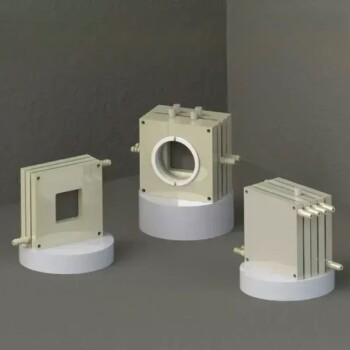
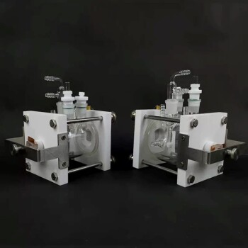
- Side Window Optical Electrolytic Electrochemical Cell
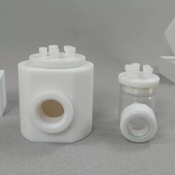
- PTFE Electrolytic Cell Electrochemical Cell Corrosion-Resistant Sealed and Non-Sealed
- Electrolytic Electrochemical Cell for Coating Evaluation
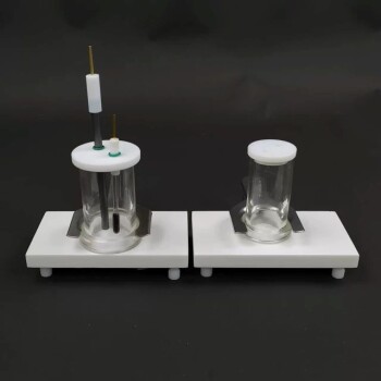
- Super Sealed Electrolytic Electrochemical Cell
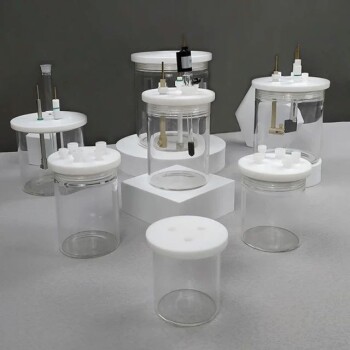
- Electrolytic Electrochemical Cell with Five-Port
Related Articles
- Escaping the Black Box: The Architecture of Insight in Electrochemistry
- The Geometry of Truth: Why the Maintenance of Your Optical Electrolytic Cell Defines Your Data
- The Art of the Finish: Why the Most Critical Moment Happens After the Data is Collected
- The Symphony of Light and Liquid: Mastering the Side-Window Electrolytic Cell
- Benefits of Electrochemical Cells for Energy Storage