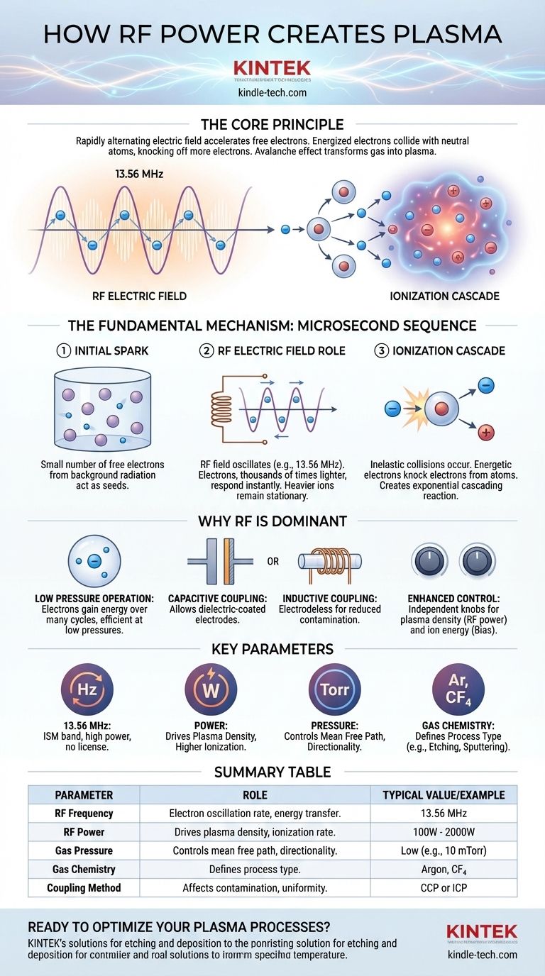
In essence, RF power creates plasma by using a rapidly alternating electric field to accelerate free electrons within a gas. These energized electrons collide with neutral gas atoms, knocking off more electrons in a cascading ionization process. This avalanche effect quickly transforms the electrically insulating gas into a quasi-neutral, conductive state of matter known as plasma.
The core principle is the continuous and efficient transfer of energy from an oscillating RF field to the electron population of a gas. Unlike a DC field, the alternating nature of RF power allows electrons to gain energy without being immediately lost to an electrode, enabling the creation of stable, high-density plasmas even at very low pressures.
The Fundamental Mechanism: From Gas to Plasma
To understand how RF power works, we must break down the process into a sequence of events that happen in microseconds. The entire mechanism is a balance between energy injection and particle interactions.
The Initial Spark: Free Electrons
Even in a pure, neutral gas, a small number of free electrons and ions always exist, created by natural background radiation. These stray charged particles are the "seeds" for the plasma. Without them, the process could not begin.
The Role of the RF Electric Field
When RF power is applied to a chamber (typically via electrodes or an antenna coil), it establishes a rapidly oscillating electric field. For a common frequency like 13.56 MHz, this field reverses direction over 13 million times per second.
Instead of being pulled in one direction as in a DC field, the free electrons are rapidly accelerated back and forth. Because electrons are thousands of times lighter than ions, they respond almost instantaneously to the changing field, while the heavier ions remain almost stationary.
The Ionization Cascade
As an electron oscillates, it gains kinetic energy from the field. When this highly energetic electron collides with a neutral gas atom, one of two things can happen:
- Elastic Collision: The electron bounces off, changing direction but retaining most of its energy.
- Inelastic Collision: If the electron has sufficient energy (exceeding the atom's ionization potential), it knocks an electron out of the atom.
This inelastic collision is the key event. It results in a positive ion and two free electrons. These two electrons are now also accelerated by the RF field, and they go on to ionize other atoms. This creates an exponential, cascading reaction that rapidly increases the density of charged particles.
Reaching a Steady State
This ionization avalanche does not continue indefinitely. It is balanced by loss mechanisms, primarily charged particles recombining into neutral atoms or colliding with the chamber walls. A stable plasma is achieved when the rate of ionization equals the rate of loss.
Why RF is the Dominant Choice for Plasma Generation
While other methods like DC discharges exist, RF has become the industry standard for most high-tech applications for several critical reasons.
Operating at Low Pressures
RF fields are exceptionally effective at sustaining plasma at low pressures (vacuum). The oscillating electrons can gain energy over many cycles, meaning they don't need to travel a long distance to become energetic enough to ionize an atom. This is crucial for semiconductor manufacturing, where long mean free paths are needed for directional etching.
Insulating Materials and Electrodes
A DC discharge requires conductive electrodes inside the plasma, which can sputter and introduce contaminants. RF power can be coupled capacitively or inductively.
- Capacitive coupling allows electrodes to be coated with a dielectric material.
- Inductive coupling allows for "electrodeless" plasmas, where the power is transferred through a dielectric window (like a quartz tube), eliminating a major source of contamination.
Enhanced Process Control
RF systems provide independent knobs for controlling critical plasma parameters. RF power primarily dictates the plasma density (the number of ions and electrons), while a separate RF or DC bias applied to the substrate can independently control the ion energy with which ions strike a surface. This decoupling is essential for tuning modern fabrication processes.
Understanding the Trade-offs and Key Parameters
Controlling an RF plasma process requires a deep understanding of several interrelated variables. Changing one parameter will almost always affect others.
Frequency: The 13.56 MHz Standard
The most common frequency used is 13.56 MHz. This is not for a magical physical reason but a practical one: it is a designated ISM (Industrial, Scientific, and Medical) band, meaning it can be used at high power without a license and won't interfere with radio communications. Other frequencies are used for specific effects on plasma chemistry and ion bombardment energy.
Power: The Driver of Density
Increasing the applied RF power directly increases the energy available to the electrons. This leads to a higher ionization rate and, consequently, a higher plasma density. In manufacturing, higher density typically translates to a faster process rate (e.g., faster etching or deposition).
Pressure: The Mean Free Path
Gas pressure determines the density of neutral atoms.
- High Pressure: More atoms, more collisions, and a shorter mean free path. This results in lower-energy electrons and more scattering, making processes less directional.
- Low Pressure: Fewer atoms and a longer mean free path. This allows electrons to gain more energy between collisions and enables ions to travel to a surface with fewer direction-altering collisions, leading to highly anisotropic (vertical) etching.
Gas Chemistry: The Process Recipe
The type of gas used is fundamental. An inert gas like Argon (Ar) is often used for physical processes like sputtering. Chemically reactive gases (e.g., CF₄, SF₆, Cl₂) are used to create specific ions and radicals that perform chemical etching on a substrate.
Making the Right Choice for Your Goal
The choice between different RF plasma source types depends entirely on the intended application and the desired outcome.
- If your primary focus is anisotropic etching with precise ion energy control (e.g., RIE in chipmaking): A Capacitively Coupled Plasma (CCP) source is the standard choice, as it naturally develops a DC self-bias that effectively accelerates ions toward the substrate.
- If your primary focus is high-rate, low-damage processing with minimal contamination (e.g., deep silicon etching or high-quality deposition): An Inductively Coupled Plasma (ICP) source is superior, as it can generate extremely dense plasma without any internal electrodes.
- If your primary focus is large-area surface treatment or cleaning where cost is a major factor: A simpler CCP system or a lower-frequency RF source often provides the most cost-effective and robust solution.
By understanding how RF energy is coupled into a gas to generate and sustain a plasma, you gain direct control over the very foundation of your process.
Summary Table:
| Parameter | Role in Plasma Generation | Typical Value/Example |
|---|---|---|
| RF Frequency | Determines electron oscillation rate; affects energy transfer efficiency. | 13.56 MHz (standard ISM band) |
| RF Power | Drives plasma density; higher power increases ionization rate. | Varies by application (e.g., 100W - 2000W) |
| Gas Pressure | Controls mean free path; influences collision frequency and directionality. | Low pressure (e.g., 10 mTorr) for anisotropic etching |
| Gas Chemistry | Defines process type (e.g., etching with CF₄, sputtering with Argon). | Argon for physical processes; CF₄ for chemical etching |
| Coupling Method | Affects contamination risk and plasma uniformity (capacitive vs. inductive). | Capacitive Coupled Plasma (CCP) or Inductively Coupled Plasma (ICP) |
Ready to Optimize Your Plasma Processes? KINTEK specializes in high-performance lab equipment, including RF plasma systems for etching, deposition, and surface treatment. Whether you need precise anisotropic etching for semiconductors or contamination-free plasma for research, our solutions deliver unmatched control and reliability. Contact our experts today to discuss your specific requirements and elevate your laboratory capabilities!
Visual Guide
Related Products
- RF PECVD System Radio Frequency Plasma-Enhanced Chemical Vapor Deposition RF PECVD
- Spark Plasma Sintering Furnace SPS Furnace
- Microwave Plasma Chemical Vapor Deposition MPCVD Machine System Reactor for Lab and Diamond Growth
- 915MHz MPCVD Diamond Machine Microwave Plasma Chemical Vapor Deposition System Reactor
- Cylindrical Resonator MPCVD Machine System Reactor for Microwave Plasma Chemical Vapor Deposition and Lab Diamond Growth
People Also Ask
- Why is a Matching Network Indispensable in RF-PECVD for Siloxane Films? Ensure Stable Plasma and Uniform Deposition
- How does Radio Frequency Enhanced Plasma Chemical Vapour Deposition (RF-PECVD) work? Learn the Core Principles
- What is the role of RF-PECVD in VFG preparation? Mastering Vertical Growth and Surface Functionality
- How does plasma enhance CVD? Unlock Low-Temperature, High-Quality Film Deposition
- What is plasma enhanced chemical vapour deposition process? Unlock Low-Temperature, High-Quality Thin Films