The design of a three-electrode electrolytic cell ensures accuracy by decoupling the catalyst's performance from the rest of the electrochemical system. By utilizing a reference electrode to control potential independently of the current-carrying counter electrode, the setup isolates the working electrode. This prevents external factors—specifically counter electrode polarization and resistance fluctuations—from skewing the stability data of the Hydrogen Evolution Reaction (HER) catalyst.
The core advantage of this configuration is isolation. It ensures that any degradation observed during long-term testing is a result of the catalyst's intrinsic failure, rather than artifacts of the experimental setup or the counter electrode.
The Mechanics of Electrochemical Isolation
The Role of the Reference Electrode
In a three-electrode system, the reference electrode acts as a stable voltage yardstick.
Crucially, it does not carry significant current. Its sole purpose is to provide a constant reference point against which the potential of the working electrode is measured and controlled.
The Role of the Counter Electrode
The counter electrode completes the electrical circuit, allowing current to flow through the electrolyte.
While necessary for the reaction, the counter electrode is prone to polarization (voltage changes due to current flow). The three-electrode design directs this instability away from the measurement circuit, rendering it irrelevant to the data collected on the catalyst.
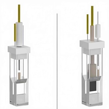
The Working Electrode
This is where your HER catalyst resides.
Because the potential is measured relative to the stable reference electrode—and not the fluctuating counter electrode—the data reflects only the events occurring at the catalyst surface.
Ensuring Data Integrity in Stability Testing
Eliminating Counter Electrode Polarization
The primary reference highlights that this design excludes the influence of counter electrode polarization.
In a two-electrode system, if the counter electrode degrades or changes resistance, the voltage reading shifts, making it look like your catalyst is failing. The three-electrode system ignores these shifts, ensuring stability data is accurate.
Filtering Out Resistance Fluctuations
Electrochemical systems often experience fluctuations in resistance (ohmic drop) over time.
By isolating the working electrode, the system prevents these systemic resistance changes from being misinterpreted as a loss of catalytic activity.
Physical Design Considerations for HER
Preventing Product Cross-Interference
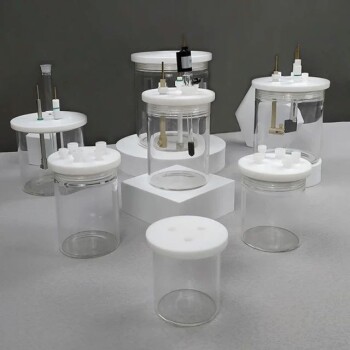
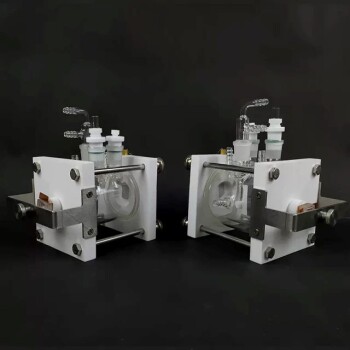
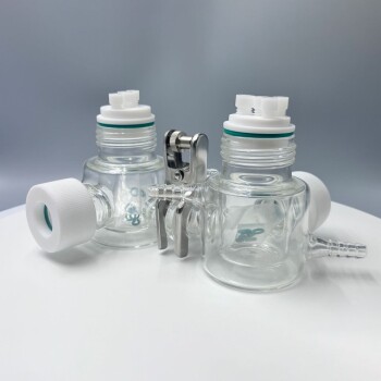
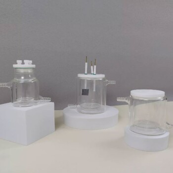
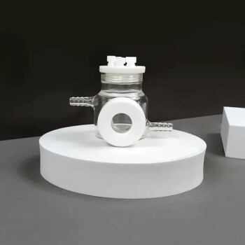
For gas-evolving reactions like HER, specialized designs such as the H-type electrolytic cell are essential.
These cells physically separate the cathode and anode chambers. This prevents oxygen evolved at the counter electrode from interfering with the hydrogen evolution at the working electrode, ensuring the chemical environment remains pure.
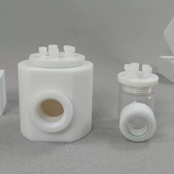
Material Purity and Visibility
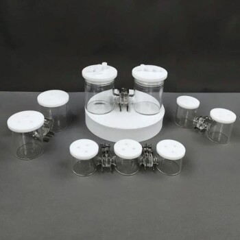
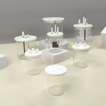
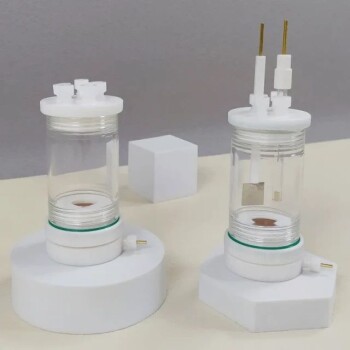
High-quality cells utilize high-transparency glass or corrosion-resistant plastic.
This allows for visual monitoring of bubble formation (gas evolution) and supports the use of high-purity consumables, minimizing the risk of contamination affecting the stability data.
Understanding the Trade-offs
Intrinsic Activity vs. Full-Cell Reality
While excellent for assessing intrinsic catalyst stability, the three-electrode cell acts as a "half-cell" model.
It decouples the catalyst from the complex environment of a full industrial electrolyzer. Therefore, excellent results here prove the material's fundamental stability but may not perfectly predict performance in a commercial membrane electrode assembly (MEA).
Uncompensated Resistance (iR Drop)
Despite the precision of the three-electrode setup, resistance between the reference and working electrodes still exists.
If not properly compensated for during data analysis (iR compensation), this resistance can still introduce minor errors in the overpotential readings, particularly at high current densities.
Making the Right Choice for Your Goal
To ensure your HER catalyst assessment is valid, align your setup with your specific research objectives:
- If your primary focus is fundamental material science: Prioritize the three-electrode H-type cell to strictly isolate the catalyst's intrinsic degradation mechanics from system noise.
- If your primary focus is industrial application: Use the three-electrode data as a baseline, but validate findings in a full-cell setup to account for membrane resistance and mass transport effects.
True accuracy in HER testing comes from measuring the catalyst, not the container.
Summary Table:
| Component | Primary Function in HER Testing | Impact on Data Accuracy |
|---|---|---|
| Working Electrode | Houses the HER catalyst under test | Direct measurement of intrinsic catalytic performance. |
| Reference Electrode | Provides a stable potential constant | Decouples catalyst potential from current-induced fluctuations. |
| Counter Electrode | Completes the electrical circuit | Prevents polarization artifacts from skewing stability data. |
| H-Type Design | Separates cathode and anode chambers | Eliminates cross-interference from evolved gases (O2 vs H2). |
Elevate Your Electrochemical Research with KINTEK Precision
Don't let experimental artifacts undermine your breakthrough. KINTEK specializes in high-performance laboratory equipment designed for rigorous material science. From our advanced electrolytic cells and electrodes specifically engineered for HER/OER stability testing to our comprehensive range of high-temperature furnaces, high-pressure reactors, and battery research tools, we provide the purity and precision your data demands.
Whether you need specialized H-type cells, corrosion-resistant consumables, or high-transparency materials for visual monitoring, KINTEK is your partner in achieving industrial-grade accuracy in a laboratory setting.
Ready to optimize your catalyst assessment? Contact KINTEK Today to explore our full portfolio of electrochemical solutions and consumables.
References
- Wenfang Zhai, Yongquan Qu. Recent progress on the long‐term stability of hydrogen evolution reaction electrocatalysts. DOI: 10.1002/inf2.12357
This article is also based on technical information from Kintek Solution Knowledge Base .
Related Products
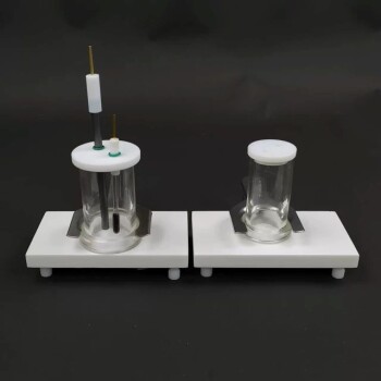
- H Type Electrolytic Cell Triple Electrochemical Cell
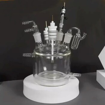
- Electrolytic Electrochemical Cell Gas Diffusion Liquid Flow Reaction Cell
- Electrolytic Electrochemical Cell with Five-Port
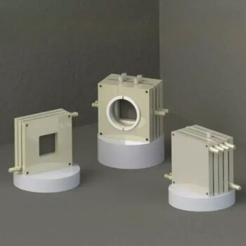
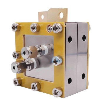
- PTFE Electrolytic Cell Electrochemical Cell Corrosion-Resistant Sealed and Non-Sealed
- Super Sealed Electrolytic Electrochemical Cell
People Also Ask
- What is a H type cell? A Guide to Divided Electrochemical Cells for Accurate Experiments
- How should failures or malfunctions of the H-type electrolytic cell be handled? Expert Troubleshooting & Repair Guide
- How should the electrolyte be prepared and added to the H-type electrolytic cell? Best Practices for Purity and Safety
- What is the typical volume range for a single chamber of the H-type electrolytic cell? Find Your Ideal Lab Capacity
- What optical features does the H-type electrolytic cell have? Precision Quartz Windows for Photoelectrochemistry