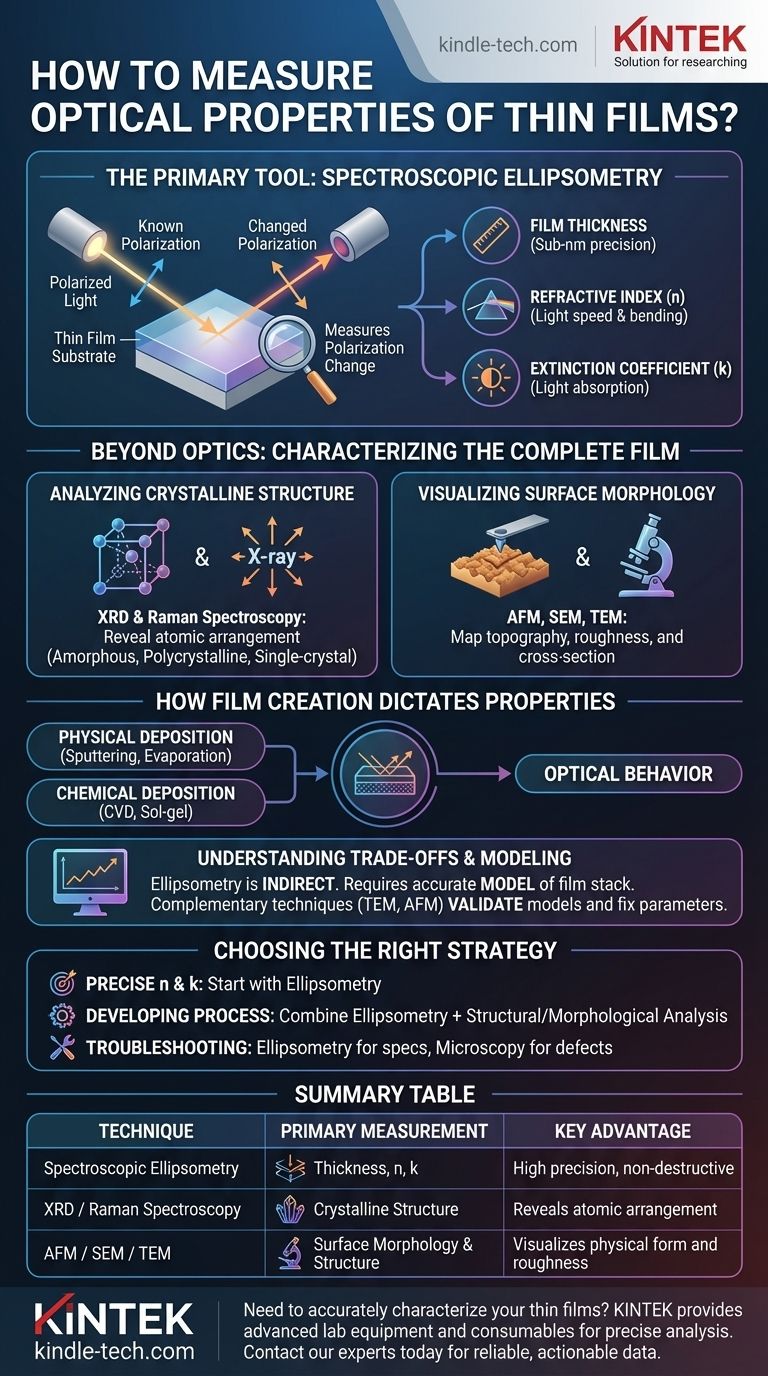
For decades, the definitive method for measuring the optical properties of thin films has been spectroscopic ellipsometry. This non-destructive technique analyzes a change in the polarization of light as it reflects from a material's surface, allowing for the precise determination of key properties like film thickness, refractive index, and the extinction coefficient.
While spectroscopic ellipsometry is the primary tool for measuring a film's optical constants, a complete characterization requires correlating these properties with the film's physical structure and the method used to create it.
The Primary Tool: Spectroscopic Ellipsometry
Spectroscopic ellipsometry is the industry and research standard for thin film optical characterization due to its high sensitivity and precision.
How It Works: Measuring a Change in Polarization
The instrument directs a beam of light with a known polarization state onto your film. After reflecting off the surface and passing through the film, the light's polarization state changes.
By measuring how much this polarization has changed across a wide range of wavelengths (spectroscopic), the system can deduce the film's properties.
What It Measures: Optical Constants and Thickness
The analysis yields three primary outputs:
- Film Thickness: Can be determined with sub-nanometer precision.
- Refractive Index (n): Describes how fast light travels through the film and how much it bends upon entry.
- Extinction Coefficient (k): Describes how much light is absorbed by the film at a given wavelength.
Together, n and k are known as the complex refractive index, or the "optical constants" of the material.
Beyond Optics: Characterizing the Complete Film
A film's optical properties do not exist in a vacuum. they are a direct consequence of its physical and chemical structure. To get a complete picture, other characterization methods are often necessary.
Analyzing Crystalline Structure
Techniques like X-ray Diffraction (XRD) and Raman Spectroscopy reveal the atomic arrangement of the film. They tell you if the material is amorphous, polycrystalline, or single-crystal, a factor that profoundly influences its optical behavior.
Visualizing Surface Morphology
Microscopy methods provide a visual understanding of the film's physical form.
Atomic Force Microscopy (AFM) maps surface topography with nanoscale resolution, quantifying roughness. Scanning Electron Microscopy (SEM) and Transmission Electron Microscopy (TEM) provide high-magnification images of the film's surface and cross-sectional structure.
How Film Creation Dictates Properties
The method used to deposit a thin film has a direct impact on its final structure and, therefore, its optical properties. Understanding the deposition process is key to interpreting measurement results.
Physical Deposition Methods
Techniques like sputtering and thermal evaporation involve bombarding or boiling a source material in a vacuum, causing it to deposit onto a substrate. These methods can create very dense and uniform films.
Chemical Deposition Methods
Processes like Chemical Vapor Deposition (CVD) and sol-gel spin coating use chemical reactions or liquid precursors to form the film. These methods allow for a wide variety of film structures, but properties are highly sensitive to precursor chemistry and temperature.
The Connection to Measurement
The chosen deposition method informs your characterization strategy. A process expected to produce a rough film, for example, necessitates AFM analysis alongside ellipsometry to build an accurate model.
Understanding the Trade-offs
While powerful, ellipsometry is not a simple "point and click" measurement. Its accuracy is dependent on the assumptions you make.
Ellipsometry's Reliance on Models
Ellipsometry is an indirect measurement technique. You must first create a mathematical model that describes your film stack (e.g., "a 100 nm layer of silicon dioxide on a silicon wafer"). The software then fits the measured data to this model to extract the thickness and optical constants.
If your model is wrong (e.g., you fail to account for a thin layer of surface roughness), the results for all other parameters will be inaccurate.
The Need for Complementary Techniques
This modeling dependency is precisely why complementary techniques are so valuable. You can use TEM to physically measure a film's thickness to validate your ellipsometry model or use AFM to measure surface roughness and fix that parameter in the model. This dramatically increases confidence in the results.
Sample Quality is Critical
For the best results, the film sample should be smooth, flat, and uniform. Highly rough, curved, or non-uniform films are extremely difficult to measure accurately with ellipsometry, as they scatter light and violate the core assumptions of the measurement model.
Choosing the Right Measurement Strategy
Your measurement plan should be guided by your ultimate goal.
- If your primary focus is obtaining precise optical constants (n and k) and thickness: Start with spectroscopic ellipsometry, as it is the most direct and powerful tool for this purpose.
- If you are developing a new film deposition process: Combine ellipsometry with structural (XRD) and morphological (AFM/SEM) analysis to understand how your process parameters affect the final film properties.
- If you are troubleshooting an optical component's performance: Use ellipsometry to verify the film's properties against its design specifications and use microscopy to check for physical defects that could be causing issues.
A comprehensive characterization strategy connects how a film is made with how it ultimately performs.
Summary Table:
| Technique | Primary Measurement | Key Advantage |
|---|---|---|
| Spectroscopic Ellipsometry | Thickness, Refractive Index (n), Extinction Coefficient (k) | High precision, non-destructive |
| XRD / Raman Spectroscopy | Crystalline Structure | Reveals atomic arrangement |
| AFM / SEM / TEM | Surface Morphology & Structure | Visualizes physical form and roughness |
Need to accurately characterize your thin films? KINTEK specializes in providing the advanced lab equipment and consumables necessary for precise optical and structural analysis. Whether you are developing new materials or troubleshooting performance, our expertise ensures you get reliable, actionable data. Contact our experts today to discuss your specific laboratory needs and find the perfect solution.
Visual Guide
Related Products
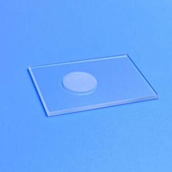
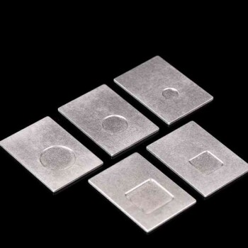
- XRD Sample Holder X-ray Diffractometer Powder Slide
- Customizable XRD Sample Holders for Diverse Research Applications
People Also Ask
- How should a sample holder be cleaned and inspected before use? Ensure Reliable Lab Results
- What is the typical function of the sample holder in an electrochemical experiment? It's the Active Working Electrode
- What is the cleaning and storage procedure for a sample holder after use? A Guide to Preventing Contamination & Damage
- What are the general operating procedures for using a sample holder during experiments? Ensure Sample Integrity and Accurate Results
- What does regular inspection of a sample holder involve for maintenance? A Guide to Protecting Your Data and Equipment