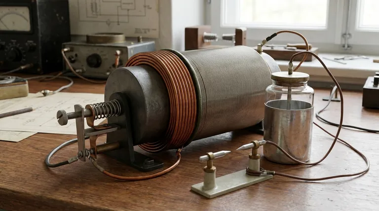
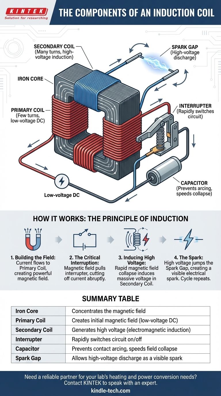
At its core, a classic induction coil is a system of six key components. These are the iron core, the primary coil, the secondary coil, an interrupter, a capacitor, and a spark gap. Together, these parts work as an electrical transformer to convert low-voltage direct current (DC) into extremely high-voltage pulses, capable of creating an electrical spark.
An induction coil isn't just a single coil; it's a complete electromechanical system. Its genius lies in using a simple switch, called an interrupter, to rapidly build and collapse a magnetic field, which in turn induces a massive voltage in a second coil.
The Core Components and Their Roles
To understand how an induction coil works, you must first understand the function of each individual part. They form a chain of events that results in a high-voltage discharge.
The Iron Core
The soft iron core sits at the center of the device. Its sole purpose is to concentrate the magnetic field lines produced by the primary coil, making the magnetic field much stronger than it would be in air alone.
The Primary Coil
This coil consists of a small number of turns (tens or hundreds) of thick copper wire wrapped around the iron core. It is connected to a low-voltage DC power source. Its job is to create the initial magnetic field when current flows through it.
The Secondary Coil
Wrapped directly on top of the primary coil, the secondary coil is made of a vast number of turns (many thousands) of very thin copper wire. This is where the high voltage is generated through electromagnetic induction. The high turn ratio between the secondary and primary coils is what amplifies the voltage.
The Interrupter (The "Heartbeat")
The interrupter is the critical switching mechanism. In classic designs, this is an electromechanical device, often a springy arm with a contact point. When current flows, the core becomes an electromagnet, pulling the arm and breaking the circuit. This is the most crucial action in the entire process.
The Capacitor
The capacitor (historically a Leyden jar) is wired in parallel with the interrupter contacts. It has two jobs: to absorb the surge of energy when the interrupter opens to prevent a damaging spark at the contacts, and to help the magnetic field collapse as quickly as possible, which maximizes the output voltage.
How the Components Work Together: The Principle of Induction
The components function in a rapid, cyclical process based on the principle of electromagnetic induction.
Step 1: Building the Magnetic Field
When the power is turned on, current flows from the source, through the interrupter's contact points, and into the primary coil. This creates a powerful magnetic field, which is concentrated by the iron core.
Step 2: The Critical Interruption
As the magnetic field builds, the iron core becomes a strong electromagnet. This magnet pulls on the interrupter's arm, breaking the electrical contact. The flow of current to the primary coil is abruptly cut off.
Step 3: Inducing the High Voltage
The sudden stop in current causes the magnetic field to collapse instantly. According to Faraday's Law of Induction, a rapidly changing magnetic field induces a voltage in any nearby coil. Because the secondary coil has thousands of times more turns, this collapsing field induces an exceptionally high voltage across it.
Step 4: The Spark
This massive voltage (tens of thousands of volts) is powerful enough to ionize the air and jump across the spark gap, creating the visible electrical spark. Once the magnetic field has collapsed, the interrupter's arm springs back, the circuit is complete again, and the entire cycle repeats itself many times per second.
Understanding the Trade-offs and Modern Variations
The classic induction coil design has evolved significantly. Understanding its limitations clarifies why modern versions are different.
Classic vs. Modern Coils
The classic electromechanical design is brilliant but has drawbacks. Modern systems, such as a car's ignition coil, use the same principle but replace the mechanical interrupter with a solid-state electronic switch, like a transistor. This is far more reliable, faster, and requires no maintenance.
Limitations of Mechanical Interrupters
The contact points on a mechanical interrupter wear down over time from the small sparks (arcing) that occur during switching. They have a limited switching speed, which caps the frequency of the sparks.
Coils for Induction Heating
The term "induction coil" can also refer to the work coil in an induction heater, as hinted at in the references. These are physically different. They are often a single, hollow copper tube coil through which water flows for cooling. Instead of an interrupter, they are driven by a high-power, high-frequency AC electronic power supply to induce heating currents in a metal workpiece placed inside the coil.
Making the Right Choice for Your Goal
The "components of an induction coil" depend on the application you have in mind.
- If your primary focus is understanding historical electronics and physics principles: The classic design with its iron core, two windings, interrupter, and capacitor is the fundamental model to study.
- If your primary focus is modern applications like automotive ignition: Recognize that the mechanical interrupter is replaced by solid-state electronics for greater reliability and control.
- If your primary focus is industrial processes like induction heating: Understand that the "coil" is a specially shaped work coil, often a single winding, driven by a separate high-frequency power source.
Ultimately, all these devices exploit the same powerful principle of electromagnetic induction to achieve their goal.
Summary Table:
| Component | Primary Function |
|---|---|
| Iron Core | Concentrates the magnetic field |
| Primary Coil | Creates the initial magnetic field with low-voltage DC |
| Secondary Coil | Generates high voltage via electromagnetic induction |
| Interrupter | Rapidly switches the circuit on/off to collapse the magnetic field |
| Capacitor | Prevents contact arcing and speeds up magnetic field collapse |
| Spark Gap | Allows the high-voltage discharge as a visible spark |
Need a reliable partner for your lab's heating and power conversion needs?
The principles behind induction coils are fundamental to many modern lab processes, from precise heating to material testing. At KINTEK, we specialize in providing high-quality lab equipment and consumables that leverage these exact principles for reliability and precision.
Whether you're working on a research project or optimizing an industrial process, our expertise can help you select the right equipment for your specific application. Let's discuss how we can support your laboratory's goals.
Contact KINTEK today to speak with an expert!
Visual Guide
Related Products
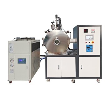
- Lab-Scale Vacuum Induction Melting Furnace
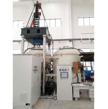
- 600T Vacuum Induction Hot Press Furnace for Heat Treat and Sintering
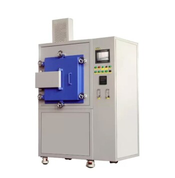
- Controlled Nitrogen Inert Hydrogen Atmosphere Furnace
People Also Ask
- What are the advantages of a vacuum induction melting furnace? Achieve High-Purity Alloys with Precision VIM
- What types of metals are typically processed in a vacuum induction melting furnace? High-Purity Alloys for Critical Applications
- What is the temperature range of the induction melting furnace? Find the Right Heat for Your Metals
- What is the function of a vacuum induction melting furnace? Essential Guide for High-Purity FeCrAl Alloy Production
- What core role does a Vacuum Induction Melting furnace play in nickel-free steel production? Achieve High-Purity Alloys