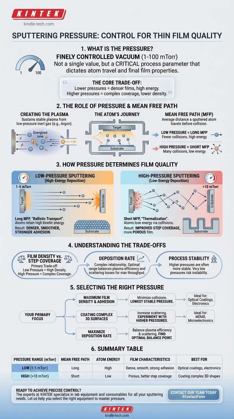
In sputtering, the working pressure is a finely controlled vacuum, typically maintained between 1 and 100 millitorr (mTorr). This is not a single fixed value but a critical process parameter that is deliberately adjusted. The chosen pressure directly dictates how sputtered atoms travel from the source material to your substrate, fundamentally determining the final properties of the deposited thin film.
The choice of sputtering pressure represents a core trade-off in thin film deposition. Lower pressures result in denser, higher-quality films by allowing atoms to travel with more energy, while higher pressures can improve the coating of complex shapes but often at the expense of film density.
The Role of Pressure in the Sputtering Process
To understand the effect of pressure, you must first understand the journey of a sputtered atom. The process begins in a vacuum chamber that is backfilled with a small amount of an inert gas, most commonly Argon.
Creating the Plasma
The sputtering process relies on a plasma, a state of matter created by energizing this low-pressure gas. The pressure must be high enough to provide enough gas atoms to sustain a stable plasma, but low enough to be considered a vacuum environment.
Defining the Mean Free Path
Once an atom is ejected from the target material, it must travel to the substrate. The most critical factor governing this journey is the mean free path (MFP).
The MFP is the average distance a particle—in this case, a sputtered atom—can travel before it collides with a background gas atom (e.g., an Argon atom).
The Link Between Pressure and Mean Free Path
The relationship is simple and direct:
- Low Pressure = Long Mean Free Path
- High Pressure = Short Mean Free Path
This single principle is the key to controlling the energy of the depositing particles and, therefore, the quality of your film.
How Pressure Determines Film Quality
The energy with which atoms arrive at the substrate surface dictates how they arrange themselves. Higher energy allows atoms to move around and find ideal locations, resulting in a superior film structure.
Low-Pressure Sputtering (High-Energy Deposition)
At lower pressures (e.g., 1-5 mTorr), the mean free path can be as long as the chamber itself. Sputtered atoms travel from the target to the substrate with few or no collisions.
This "ballistic" transport means the atoms retain most of their initial high kinetic energy. This energetic bombardment leads to films that are denser, smoother, and exhibit stronger adhesion to the substrate.
High-Pressure Sputtering (Low-Energy Deposition)
At higher pressures (e.g., >10 mTorr), the mean free path becomes very short. A sputtered atom will undergo numerous collisions with gas atoms on its way to the substrate.
Each collision transfers energy away from the sputtered atom. The atoms arrive at the substrate with very low energy, a process known as "thermalization."
This scattering causes atoms to arrive from many different angles. While this can improve step coverage—the ability to coat the sidewalls of trenches or other complex 3D features—it typically results in a more porous and less dense film.
Understanding the Trade-offs
Adjusting the pressure is never about finding one "correct" value; it is about balancing competing objectives.
Film Density vs. Step Coverage
This is the primary trade-off. For applications demanding high performance, such as optical coatings or electrical conductors, maximizing density is crucial, pushing you toward lower pressures. For coating complex topographies in MEMS or microelectronics, you may need to increase pressure to ensure adequate coverage, accepting a potential decrease in film density.
Deposition Rate
The relationship between pressure and deposition rate is complex. At very low pressures, it can be difficult to sustain a dense, efficient plasma, which can reduce the rate. Conversely, at very high pressures, excessive scattering can prevent sputtered atoms from reaching the substrate, also reducing the rate. There is often an optimal pressure range for maximizing throughput.
Process Stability
Maintaining a stable plasma discharge is generally easier at slightly higher pressures. Operating at the lowest possible pressures can sometimes risk process instability, where the plasma can flicker or extinguish. Your system's capabilities will define the lower bound of your practical working range.
Selecting the Right Pressure for Your Application
Your choice of pressure should be driven entirely by the desired outcome for your thin film.
- If your primary focus is maximum film density and adhesion: Your goal is to minimize in-flight collisions. You should operate at the lowest stable pressure your system can achieve to ensure a high-energy, ballistic deposition.
- If your primary focus is coating complex 3D surfaces: Your goal is to increase atomic scattering. You should experiment with higher working pressures to improve step coverage, even if it results in a less dense film.
- If your primary focus is maximizing deposition rate: You must find the optimal balance point for your specific material and system, where the plasma is efficient but scattering losses are not yet dominant.
Ultimately, sputtering pressure is your primary lever for controlling the energy delivered to the substrate, allowing you to engineer the microstructure of your film.
Summary Table:
| Pressure Range (mTorr) | Mean Free Path | Atom Energy | Film Characteristics | Best For |
|---|---|---|---|---|
| Low (1-5 mTorr) | Long | High | Dense, smooth, strong adhesion | Optical coatings, electronics |
| High (>10 mTorr) | Short | Low | Porous, better step coverage | Coating complex 3D shapes |
Ready to achieve precise control over your thin film properties? The experts at KINTEK specialize in lab equipment and consumables for all your sputtering and deposition needs. Whether you're developing optical coatings, MEMS devices, or advanced electronics, we can help you select the right equipment to master critical parameters like pressure. Contact our team today to discuss how we can support your laboratory's success.
Visual Guide
Related Products
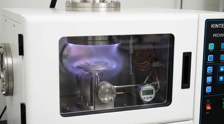
- Chemical Vapor Deposition CVD Equipment System Chamber Slide PECVD Tube Furnace with Liquid Gasifier PECVD Machine
- Twin Screw Extruder Plastic Granulation Machine
- Three-dimensional electromagnetic sieving instrument
- Single Punch Manual Tablet Press Machine TDP Tablet Punching Machine
- Single Punch Electric Tablet Press Machine TDP Tablet Punching Machine
People Also Ask
- How expensive is chemical vapor deposition? Understanding the True Cost of High-Performance Coating
- How are carbon nanotubes grown? Master Scalable Production with Chemical Vapor Deposition
- What are the processes of vapor phase deposition? Understand CVD vs. PVD for Superior Thin Films
- What is the chemical vapor deposition growth process? Build Superior Thin Films from the Atom Up
- What are the advantages of chemical vapor deposition? Achieve Superior Thin Films for Your Lab