Slender PTFE tubing serves as a critical passive flow regulator to ensure identical gas distribution across multiple reactor channels. In parallel catalyst aging tests, these tubes function as high-resistance throttles. By generating a backpressure that significantly exceeds the resistance of the catalyst beds themselves, the tubing forces gas to flow equally into every channel, regardless of variations in how the catalyst is packed.
By creating a dominant pressure drop upstream of the reactor, the tubing renders minor inconsistencies in catalyst bed density irrelevant. This guarantees that test data reflects actual catalyst performance rather than random fluctuations in gas flow.
The Physics of Flow Equalization
Overcoming Packing Variability
In any multi-channel system, catalyst beds are never packed with perfect identicality. Slight differences in packing density create "paths of least resistance."
Without intervention, gas would naturally flow preferentially through the loosely packed channels, starving the denser ones. This creates biased data that invalidates the comparison between catalysts.
The Principle of Dominant Resistance
The slender PTFE tubing acts as a capillary flow limiter. It is designed to generate a specific, high backpressure (often around 2 bar).
This artificial resistance is engineered to be significantly higher than the natural resistance of the catalyst bed. Consequently, the total resistance of the system is dictated by the precise length of the tubing, not the variable state of the catalyst bed.
Ensuring Fair Comparisons
Catalyst aging tests are effectively endurance runs, often lasting 168 hours or more.
By hydraulically locking the flow rate through fixed tubing resistance, researchers ensure that every channel receives the exact same "load" over the entire duration. This makes the resulting degradation data fair and directly comparable.
Material Selection for Reliability
Resistance to Corrosive Environments
The choice of material is as critical as the dimensions of the tubing. Catalyst testing often involves aggressive feed gases, such as hydrogen chloride.
PTFE (Polytetrafluoroethylene) is selected for its chemical inertness. Unlike metal capillaries, PTFE resists corrosion and prevents the formation of reaction byproducts that could clog the narrow passage or contaminate the catalyst downstream.
Prevention of Flow Drift
Because PTFE does not degrade in the presence of these harsh chemicals, the internal diameter of the tubing remains constant.
This ensures that the flow rate does not drift over time due to material erosion or buildup, maintaining the integrity of long-term aging studies.
Understanding the Trade-offs
System Pressure Requirements
Using capillaries to generate ~2 bar of backpressure places a higher demand on the gas supply system.
The upstream pressure regulators must be capable of delivering stable flow at pressures high enough to overcome this intentional bottleneck.
Lack of Dynamic Control
Unlike electronic mass flow controllers, PTFE tubing is a passive, fixed-resistance solution.
Changing the flow rate significantly usually requires physically changing the length or diameter of the tubing. This offers high reliability and low cost but sacrifices dynamic flexibility during a run.
Making the Right Choice for Your Goal
To ensure the validity of your multi-channel reactor data, consider the following regarding your flow control setup:
- If your primary focus is Data Accuracy: Ensure all PTFE tubes are cut to precisely the same length to guarantee identical resistance across channels.
- If your primary focus is Chemical Compatibility: Verify that the PTFE grade used is rated for the specific corrosive nature of your feed gas (e.g., HCl concentrations) to prevent long-term embrittlement.
The use of slender PTFE tubing effectively decouples flow control from reactor variables, providing a robust, fail-safe method for parallel experimentation.
Summary Table:
| Feature | Function in Catalyst Testing | Benefit to Research |
|---|---|---|
| Passive Flow Regulation | Creates a dominant pressure drop (e.g., ~2 bar) | Neutralizes packing density variability |
| PTFE Material | Resists corrosive feed gases like HCl | Prevents contamination and flow drift |
| Fixed Resistance | Maintains constant capillary flow | Ensures identical loading over 168+ hour tests |
| Hydraulic Locking | Decouples flow control from reactor variables | Guarantees data accuracy and comparability |
Maximize Your Research Precision with KINTEK
Ensure the integrity of your parallel catalyst studies with KINTEK’s high-performance laboratory solutions. From chemically inert PTFE products and precision-engineered consumables to advanced high-temperature reactors and catalysts aging systems, we provide the tools necessary to eliminate experimental bias.
Whether you need robust high-pressure reactors, specialized crushing and milling systems, or precise homogenizers, KINTEK is your partner in achieving repeatable, high-accuracy data.
Ready to upgrade your lab's flow control and thermal processing? Contact KINTEK today for expert guidance and tailored equipment solutions!
References
- Thomas J. Lenk, Santiago Casu. A High-Throughput Screening Approach to Identify New Active and Long-Term Stable Catalysts for Total Oxidation of Methane from Gas-Fueled Lean–Burn Engines. DOI: 10.3390/catal10020159
This article is also based on technical information from Kintek Solution Knowledge Base .
Related Products
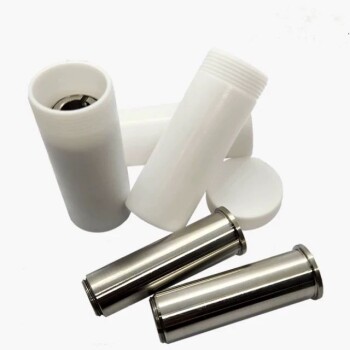
- Custom PTFE Teflon Parts Manufacturer for PTFE Bottle Oil Fume Sampling Tube
- Custom PTFE Teflon Parts Manufacturer for Centrifuge Tubes
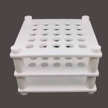
- Custom PTFE Teflon Parts Manufacturer for Centrifuge Tube Racks
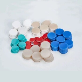
- Custom PTFE Teflon Parts Manufacturer for Gaskets and More
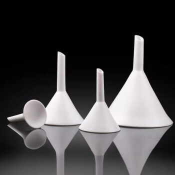
- Custom PTFE Teflon Parts Manufacturer for PTFE Buchner Funnel and Triangular Funnel
People Also Ask
- What makes PTFE bottles suitable for static leaching? Ensure Zero-Contamination for Glass Testing
- What are the advantages of using PTFE lined tubing? Optimize Sample Integrity & Reduce Memory Effects
- Why Use PTFE Sample Bottles for Coal Demineralization? Ensure Chemical Stability and Data Integrity
- What is the significance of using PTFE gas tubing for HCl? Ensure Pure, Corrosion-Free Salt Formation
- What is the function of PTFE in a gas diffusion electrode? Mastering CO2 Electrolyzer Stability