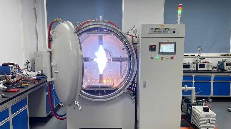
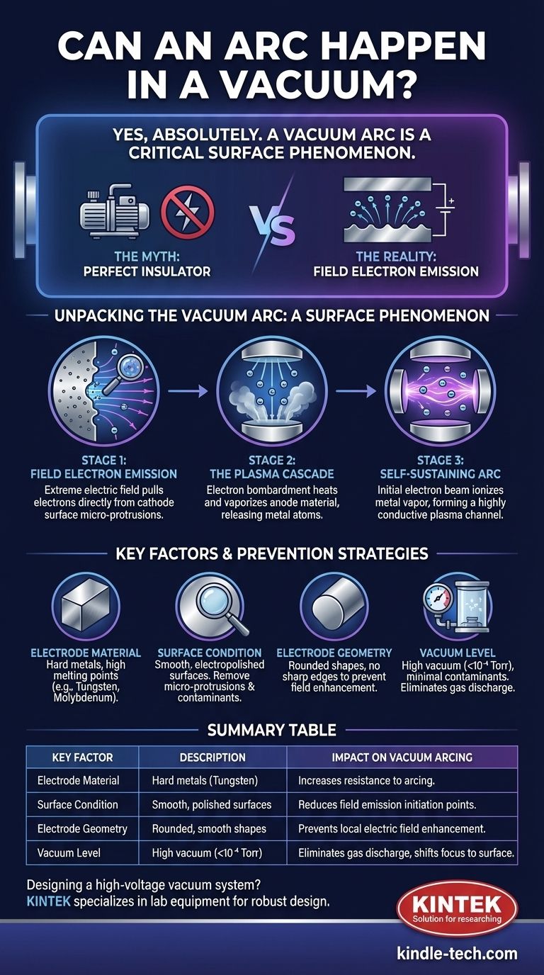
Yes, an electrical arc can absolutely happen in a vacuum. In fact, this phenomenon, known as a vacuum arc, is a critical design constraint in high-voltage applications ranging from particle accelerators to spacecraft. While a perfect vacuum is an excellent insulator, the breakdown mechanism is fundamentally different and more complex than an arc in air, as it originates from the electrode surfaces themselves, not the space between them.
A vacuum is often thought of as the ultimate insulator, but this is a misconception. An electrical arc in a vacuum is not caused by the breakdown of residual gas, but by the electric field becoming so intense that it rips electrons and eventually vaporized metal directly from the electrode surfaces, creating a conductive plasma channel.
The Myth of the Perfect Insulator
A common assumption is that removing all gas molecules from a space removes the medium for an electrical current to flow, preventing an arc. While this is true for low-voltage scenarios, it fails at high voltages.
How Arcs Form in Gas (The Baseline)
In air or another gas, an arc typically forms when an electric field accelerates free electrons. These electrons collide with gas molecules, knocking more electrons loose in an avalanche process called gas discharge.
This behavior is well-described by Paschen's Law, which shows that the voltage needed to start an arc depends on the product of gas pressure and gap distance. As you lower the pressure, the breakdown voltage actually increases significantly because there are fewer molecules to collide with.
The Transition to Vacuum Breakdown
However, once you reach a very high vacuum (typically below 10⁻⁴ Torr), there are so few gas molecules that the Paschen's Law mechanism becomes irrelevant. An electron could cross the entire gap without hitting a single molecule.
At this point, a different and more subtle mechanism takes over: field electron emission.
Unpacking the Vacuum Arc: A Surface Phenomenon
A vacuum arc is a multi-stage process that begins and ends with the electrodes. The vacuum itself is merely the arena where the event unfolds.
Stage 1: Field Electron Emission
Even at room temperature, an extremely strong electric field (on the order of gigavolts per meter) can pull electrons directly out of the atoms of a metal conductor. This quantum mechanical effect is known as field emission.
These electrons are "tunneled" out of the cathode surface by the sheer force of the electric field, creating an initial stream of current across the vacuum gap.
Stage 2: The Role of Surface Imperfections
Real-world electrode surfaces are never perfectly smooth. They are covered in microscopic points, ridges, and contaminants.
These microscopic protrusions act like tiny lightning rods, dramatically concentrating the electric field. A moderate average field across a gap can become an immense local field at the tip of one of these micro-points, initiating field emission long before the theoretical limit for a perfect surface is reached.
Stage 3: The Plasma Cascade
Once field emission begins, the emitted electrons accelerate across the gap and bombard the anode (the positive electrode) with tremendous energy. This intense bombardment heats a tiny spot on the anode to its boiling point.
This heating vaporizes a small amount of the anode material, releasing a plume of neutral metal atoms into the vacuum gap. The initial electron beam then collides with and ionizes this metal vapor, creating a highly conductive mixture of electrons and positive metal ions—a plasma.
This self-sustaining plasma is the vacuum arc. It provides a low-resistance path that can carry an enormous current, fed by material vaporizing from both electrodes.
Key Factors and Prevention Strategies
Preventing a vacuum arc is not about improving the vacuum but about managing the electrodes and the electric field.
Electrode Material and Conditioning
Hard metals with high melting points and low vapor pressures, such as tungsten and molybdenum, are more resistant to arcing than softer metals like aluminum or copper.
Furthermore, surfaces must be meticulously prepared. This involves electropolishing to remove micro-points and baking the components under vacuum to drive out trapped gases and contaminants. A process called conditioning—running a controlled, current-limited discharge to systematically burn off the sharpest protrusions—is a standard practice in high-voltage vacuum systems.
The Importance of Geometry
Sharp edges and corners must be avoided in any high-voltage vacuum design. All conductive surfaces should have large, smooth radii.
Engineers use specialized shapes, like Rogowski profiles, for electrodes to ensure the electric field is as uniform as possible and to prevent local field enhancements that could trigger an arc.
The "Total Voltage" Effect
Counter-intuitively, for very large gaps (centimeters to meters), the breakdown can sometimes be triggered by the total voltage across the gap, not just the local electric field strength. This is a complex phenomenon where a single microparticle breaking loose can be enough to initiate a breakdown cascade across a very large distance.
Making the Right Choice for Your Design
Your strategy for mitigating vacuum arcs depends entirely on your application's specific constraints and failure modes.
- If your primary focus is high-power reliability (e.g., accelerators, transmitters): Your priority is meticulous material selection and surface preparation, including polishing, cleaning, and in-situ high-voltage conditioning.
- If your primary focus is compact electronics (e.g., satellite components): Your priority is managing geometry by eliminating all sharp edges, maximizing clearance, and using smooth, rounded conductors.
- If your primary focus is process integrity (e.g., vacuum deposition, SEM): Your priority is maintaining ultra-high vacuum quality and ensuring all components are thoroughly outgassed to minimize surface contaminants that can lower the arc threshold.
Ultimately, preventing an arc in a vacuum is an exercise in controlling the electrode surfaces and managing the shape of the electric field.
Summary Table:
| Key Factor | Description | Impact on Vacuum Arcing |
|---|---|---|
| Electrode Material | Hard metals like tungsten with high melting points. | Increases resistance to arcing. |
| Surface Condition | Smooth, polished surfaces without micro-protrusions. | Reduces field emission initiation points. |
| Electrode Geometry | Rounded, smooth shapes (e.g., Rogowski profiles). | Prevents local electric field enhancement. |
| Vacuum Level | High vacuum (below 10⁻⁴ Torr) with minimal contaminants. | Eliminates gas discharge, shifts focus to surface phenomena. |
Designing a high-voltage vacuum system? Don't let vacuum arcing compromise your project's reliability. KINTEK specializes in lab equipment and consumables, providing the high-quality components and expertise needed for robust vacuum system design. Our products are engineered to meet the stringent demands of laboratories, ensuring superior performance and longevity. Contact us today to discuss how we can support your specific application and help you achieve optimal results.
Visual Guide
Related Products
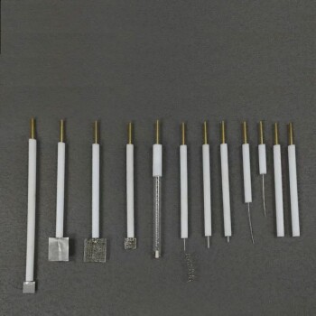
- CF KF Flange Vacuum Electrode Feedthrough Lead Sealing Assembly for Vacuum Systems
- Ultra-Vacuum Electrode Feedthrough Connector Flange Power Electrode Lead for High-Precision Applications
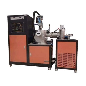
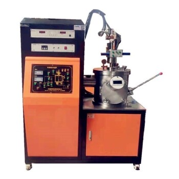
- Vacuum Arc Induction Melting Furnace
- Non Consumable Vacuum Arc Induction Melting Furnace
- Vacuum Induction Melting Spinning System Arc Melting Furnace
People Also Ask
- Under what pressure value does vacuum system operate in instrumentation? Find the Perfect Range for Your Lab
- What are the considerations for vacuum system design? Achieve Optimal Performance for Your Lab
- What are the factors that affect the strength of a brazed joint? Master the 4 Keys to a Perfect Bond
- What is the purpose of a vacuum system? Achieve Unmatched Process Control and Purity
- What is the importance of leakage in a vacuum system? Prevent Contamination and Process Failure