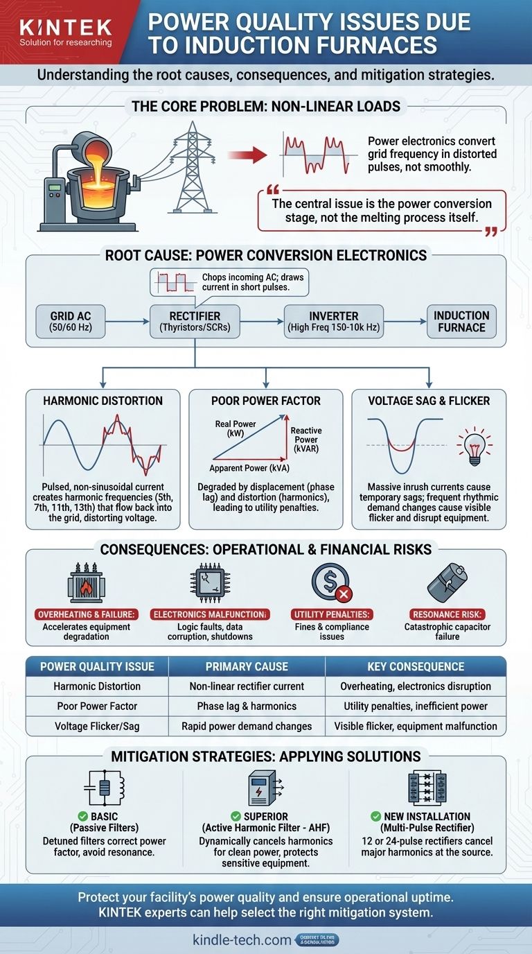
At their core, induction furnaces create significant power quality problems primarily because they are large, non-linear loads. The power electronics used to convert standard grid frequency into the high frequency needed for melting do not draw current smoothly; instead, they draw it in distorted pulses, leading to harmonic distortion, a poor power factor, and voltage fluctuations that can disrupt the electrical grid and nearby equipment.
The central issue is not the furnace's melting process itself, but the power conversion stage that feeds it. The rectifier and inverter systems fundamental to the furnace's operation are the primary sources of electrical disturbances that must be managed.
The Root Cause: Power Conversion Electronics
An induction furnace cannot use grid power directly. It requires a power supply that converts the standard 50/60 Hz AC from the utility into the medium- or high-frequency AC (150 Hz to 10,000 Hz) needed to induce heat in the metal charge. This conversion process is the source of nearly all power quality issues.
The Role of the Rectifier
The first step in the conversion is the rectifier, which converts incoming AC power to DC power. Most large furnaces use phase-controlled rectifiers built with thyristors (SCRs).
These devices control the furnace's power by "chopping up" the incoming AC voltage waveform. They only conduct for a portion of each cycle, resulting in current being drawn in short, sharp pulses rather than a smooth sine wave.
The Source of Harmonic Distortion
This pulsed, non-sinusoidal current draw is the definition of harmonic distortion. The distorted current wave is composed of the fundamental frequency (50/60 Hz) plus multiple integer frequencies (100/120 Hz, 150/180 Hz, etc.).
These harmonic currents flow back into the power grid, distorting the voltage for all users on the same circuit. The most problematic harmonics for a standard 6-pulse rectifier are the 5th, 7th, 11th, and 13th.
The Double Problem of Power Factor
Induction furnaces degrade power factor in two ways, resulting in a very low overall power factor, often below 0.80.
- Displacement Power Factor: The thyristor control causes a phase lag between the voltage and the fundamental current, creating a poor displacement power factor.
- Distortion Power Factor: The presence of harmonic currents means that not all the current is doing useful work, which lowers the distortion power factor.
Utilities often impose significant financial penalties for low power factor because it forces them to supply more apparent power (kVA) than the real power (kW) being consumed, straining their infrastructure.
Voltage Sag and Flicker
The melting cycle of a furnace involves massive and rapid changes in power demand. When a large charge is added or the furnace is first powered on, it draws an immense inrush current.
This sudden high current draw causes a temporary voltage drop, or sag, on the local grid. If these power fluctuations are frequent and rhythmic, they cause a phenomenon known as voltage flicker, which is visible as a pulsing in lighting and can disrupt sensitive electronic equipment.
Understanding the Consequences
Ignoring these power quality issues is not an option, as they lead to tangible operational and financial problems.
Overheating and Equipment Failure
Harmonic currents cause additional heating in transformers, conductors, and motors. This excess heat accelerates the degradation of insulation and can lead to premature and unexpected equipment failure.
Malfunction of Sensitive Electronics
Modern industrial plants rely on PLCs, computers, and variable frequency drives (VFDs). The voltage distortion caused by harmonics can lead to logic faults, data corruption, and complete shutdown of these critical control systems.
Utility Penalties and Compliance Issues
Most electrical utilities have strict limits on the amount of harmonic distortion a customer can inject into the grid (e.g., IEEE 519 standard). Failing to comply can result in heavy fines or even the threat of disconnection.
The Critical Risk of Resonance
A common but incorrect solution is to simply add power factor correction capacitors. The inductance of the utility transformer combined with these capacitors creates a resonant circuit. If this circuit's resonant frequency is close to one of the furnace's dominant harmonics (like the 5th or 7th), the harmonic current can be massively amplified, leading to catastrophic failure of capacitors and other equipment.
How to Apply This to Your Project
The right mitigation strategy depends on your budget, the scale of your operation, and the strictness of your utility's requirements.
- If your primary focus is meeting basic utility requirements on a budget: Consider a system of detuned passive harmonic filters, which are designed to correct power factor while avoiding resonance with the most problematic harmonics.
- If your primary focus is protecting sensitive equipment and maximizing uptime: An Active Harmonic Filter (AHF) is the superior solution, as it dynamically cancels harmonic currents across a wide spectrum to ensure clean power.
- If you are designing a new, large-scale installation: Specify a furnace with a 12-pulse or 24-pulse rectifier, which inherently cancels major low-order harmonics at the source and drastically reduces the need for external filtering.
Proactively managing the power quality of an induction furnace is a direct investment in the reliability and efficiency of your entire facility.
Summary Table:
| Power Quality Issue | Primary Cause | Key Consequence |
|---|---|---|
| Harmonic Distortion | Non-linear current draw from rectifiers | Overheating of equipment, disruption of sensitive electronics |
| Poor Power Factor | Phase lag and harmonic currents | Utility penalties, inefficient power use |
| Voltage Flicker/Sag | Rapid, large changes in power demand | Visible light pulsing, equipment malfunctions |
Protect your facility's power quality and ensure operational uptime. The power disturbances from induction furnaces—like harmonic distortion and voltage flicker—can lead to costly equipment failure and utility penalties. KINTEK specializes in lab equipment and consumables, serving the precise power needs of industrial and research laboratories. Our experts can help you select the right mitigation systems, from passive filters to active harmonic solutions, tailored to your specific furnace and compliance requirements. Don't let power quality issues disrupt your critical processes—contact us today for a consultation and ensure your lab's power is as reliable as your results.
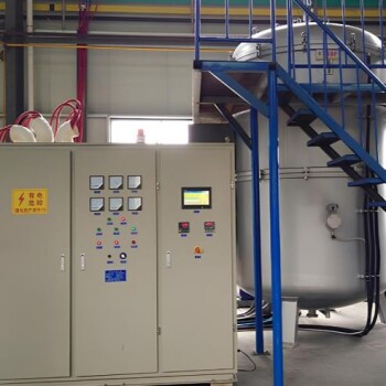
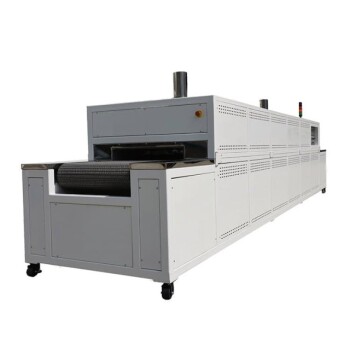
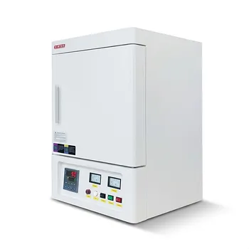
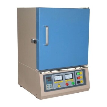
Visual Guide
Related Products
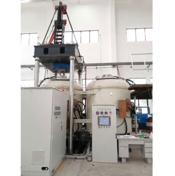
- 600T Vacuum Induction Hot Press Furnace for Heat Treat and Sintering
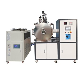
- Lab-Scale Vacuum Induction Melting Furnace
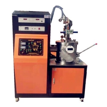
- Non Consumable Vacuum Arc Induction Melting Furnace
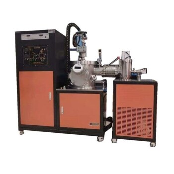
- Vacuum Arc Induction Melting Furnace
- Controlled Nitrogen Inert Hydrogen Atmosphere Furnace
People Also Ask
- How does the vacuum system within a vacuum hot press furnace contribute to the quality of aluminum matrix composites?
- What core challenges does a vacuum hot press furnace address? Achieve Superior WCp/Cu FGM Structural Integrity
- What are the advantages of a vacuum hot press furnace for W-50%Cu? Achieve 99.6% Density at Lower Temperatures
- What role does an induction vacuum hot pressing furnace play in sintering? Achieve 98% Density in Carbide Blocks
- What role does mechanical pressure play during the vacuum diffusion bonding of tungsten and copper? Keys to Solid Bonding