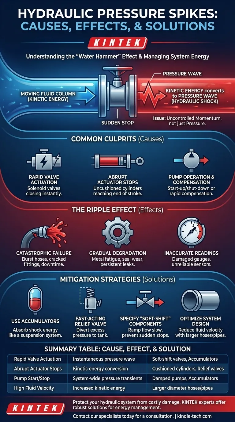
At its core, a hydraulic pressure spike is caused by a sudden, forceful change in the speed of the fluid within your system. This event, often called hydraulic shock or water hammer, happens when a moving column of hydraulic oil is forced to stop or rapidly change direction, causing its kinetic energy to convert into a massive, instantaneous pressure wave.
The fundamental issue isn't pressure itself, but rather the uncontrolled momentum of the fluid. Understanding that hydraulic spikes are an energy management problem—not just a pressure problem—is the key to preventing catastrophic system damage.
The Physics of a Pressure Spike: From Motion to Force
To properly diagnose and prevent pressure spikes, you must first understand the physics at play. The phenomenon is a direct result of energy transformation within a confined, nearly incompressible fluid.
The "Water Hammer" Effect
The most intuitive analogy is the "water hammer" effect in household plumbing. When you quickly shut a faucet, you might hear a loud bang in the pipes. That noise is the shockwave created as the moving water column crashes to a halt, sending a high-pressure wave back through the pipe. Hydraulic systems experience the exact same event, but at vastly higher pressures and with potentially destructive force.
Kinetic Energy Conversion
A moving column of hydraulic fluid possesses kinetic energy (energy of motion). When a valve slams shut or a cylinder hits its end of stroke, that motion is arrested almost instantly. Because energy cannot be destroyed, this kinetic energy must be converted into another form.
The Role of Fluid Incompressibility
Hydraulic oil is prized for its near-incompressibility. While this is excellent for transmitting power, it means there is almost no "give" in the system to absorb the energy from a sudden stop. Instead, the energy is converted into potential energy in the form of an extreme pressure rise that can be many times the system's normal operating pressure.
Common Culprits in Your Hydraulic System
While the principle is universal, the cause of hydraulic shock is almost always tied to the rapid action of a specific component.
Rapid Valve Actuation
This is the number one cause of pressure spikes. Solenoid-operated directional control valves, which can shift in milliseconds, are notorious for this. Suddenly closing a valve in the path of high-velocity fluid is the classic recipe for a dangerous pressure transient.
Abrupt Actuator Stops
When a hydraulic cylinder reaches the end of its travel at high speed without any cushioning, it causes the fluid pushing it to stop instantaneously. Likewise, a hydraulic motor that is brought to a sudden halt by an external load or brake will generate a significant pressure spike on its inlet side.
Pump Operation and Compensation
The start-up or shut-down of a high-flow pump can introduce pressure waves into a system. More subtly, the action of a pressure-compensating pump can be a source. As the compensator rapidly de-strokes the pump to reduce flow at the set pressure, it can create a shock event if not properly damped.
Understanding the Trade-offs: The Ripple Effect of Pressure Spikes
Ignoring pressure spikes doesn't just risk a single component failure; it introduces systemic unreliability and danger.
Catastrophic Component Failure
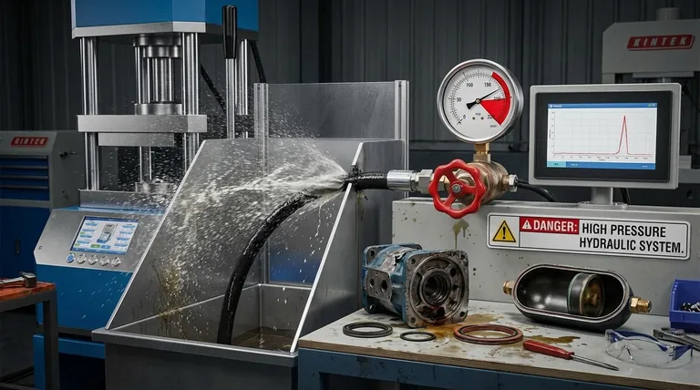
The most obvious consequence is immediate, catastrophic failure. A pressure spike can easily burst a hydraulic hose, crack a fitting, or even fracture a valve body or pump housing. These failures result in costly downtime and significant safety hazards from high-pressure fluid injection.
Gradual System Degradation
Not all spikes lead to a single dramatic event. Repeated, lower-level spikes cause metal fatigue and micro-fractures in rigid components. They also lead to premature wear on seals, O-rings, and other soft parts, resulting in persistent leaks and a system that constantly requires maintenance.
Inaccurate System Readings
Pressure gauges and electronic pressure transducers are sensitive instruments. A powerful pressure spike can permanently damage them, bending the needle on a gauge or destroying the diaphragm in a sensor. This leaves you operating blind, unable to trust your system's instrumentation.
Mitigation Strategies: Taming Hydraulic Shock
The goal is to manage the fluid's energy. You can either slow the rate of energy change or provide a path for the excess energy to be safely absorbed.
Using Accumulators as a Cushion
An accumulator is the most effective tool. This component contains a nitrogen gas-charged bladder that acts as a shock absorber. When a pressure wave hits, the gas compresses, absorbing the excess energy and releasing it smoothly back into the system. It is the hydraulic equivalent of a suspension system.
Installing a Fast-Acting Relief Valve
A pressure relief valve acts as a safety limiter. Placed near the source of the shock, it will open momentarily when pressure exceeds its setting, diverting flow back to the tank and "clipping" the top off the pressure spike. However, it must be a very fast-acting, direct-operated relief valve to respond quickly enough.
Specifying "Soft-Shift" Components
Many manufacturers offer "soft-shift" or "soft-start" valves that are engineered to shift more slowly. By ramping the flow up or down over a few hundred milliseconds instead of instantly, they prevent the sudden stop that causes the shock in the first place. Similarly, cushioned cylinders have built-in dampers that slow the piston down just before it reaches the end of its stroke.
Optimizing System Design
Good design can minimize the potential for shock. Using larger diameter hoses or pipes for a given flow rate reduces the fluid's velocity, which in turn reduces its kinetic energy. Incorporating sections of flexible hose can also help absorb some shock energy compared to entirely rigid tubing.
Making the Right Choice for Your Goal
Your approach to mitigation depends on whether you are fixing an existing problem or designing a new, reliable system.
- If your primary focus is fixing sudden, catastrophic failures: Your priority is immediate energy absorption. Install a properly sized accumulator or a fast-acting relief valve as close as possible to the component causing the shock.
- If your primary focus is eliminating persistent leaks and premature wear: Your goal is to reduce the intensity of operational shocks. Investigate replacing standard valves with soft-shift models or using cushioned cylinders.
- If your primary focus is designing a resilient new system: Proactively design to reduce fluid velocity from the start and strategically place accumulators near fast-acting valves and motors to prevent shock from ever becoming a problem.
By treating hydraulic spikes as a fundamental issue of energy control, you can effectively design and maintain a safer, more reliable system.
Summary Table:
| Cause | Effect | Solution |
|---|---|---|
| Rapid Valve Actuation | Instantaneous pressure wave | Soft-shift valves, Accumulators |
| Abrupt Actuator Stops | Kinetic energy conversion | Cushioned cylinders, Relief valves |
| Pump Start/Stop | System-wide pressure transients | Damped pumps, Accumulators |
| High Fluid Velocity | Increased kinetic energy | Larger diameter hoses/pipes |
Protect your hydraulic system from costly damage and downtime. The experts at KINTEK understand that pressure spikes are an energy management challenge. We specialize in providing robust lab equipment and consumables, including hydraulic system components designed for reliability and safety. Let us help you select the right accumulators, valves, or system design solutions to tame hydraulic shock.
Contact our specialists today for a consultation and ensure your system's longevity.
Visual Guide
Related Products
- Manual High Temperature Heated Hydraulic Press Machine with Heated Plates for Lab
- Automatic High Temperature Heated Hydraulic Press Machine with Heated Plates for Lab
- Heated Hydraulic Press Machine with Heated Plates for Vacuum Box Laboratory Hot Press
- Ball Press Mold for Lab
- 24T 30T 60T Heated Hydraulic Press Machine with Heated Plates for Laboratory Hot Press
People Also Ask
- What does a hydraulic heat press do? Achieve Industrial-Scale, Consistent Pressure for High-Volume Production
- What is a hot hydraulic press? Harness Heat and Pressure for Advanced Manufacturing
- What are heated hydraulic presses used for? Molding Composites, Vulcanizing Rubber, and More
- What is the core function of a laboratory heated hydraulic press in CSP? Revolutionize Low-Temp Ceramic Sintering
- Why is the heating function of a laboratory hydraulic press essential for MEA assembly in DEFC? Optimize Cell Bonding