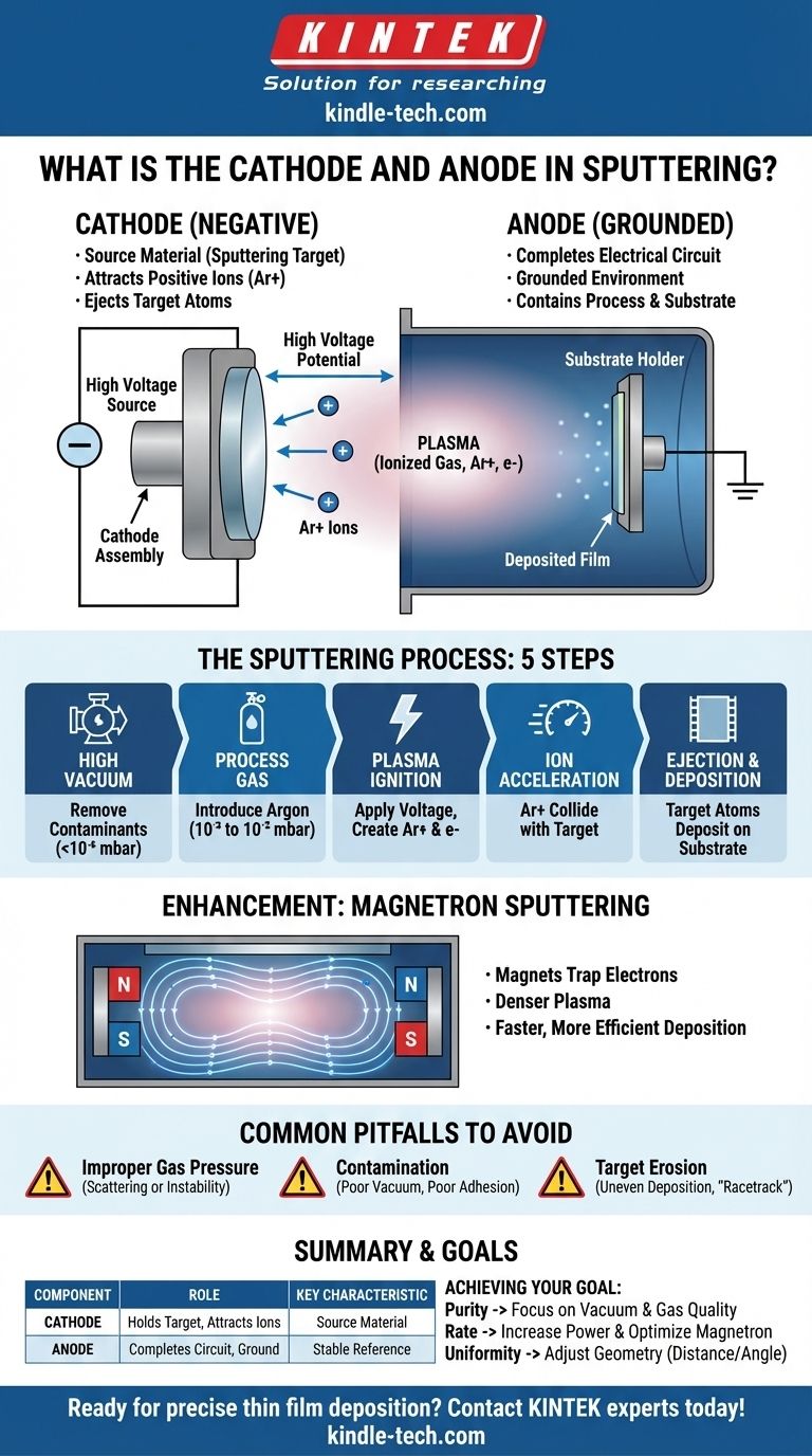
In sputtering, the cathode is the negatively charged electrode that holds the source material you intend to deposit, known as the sputtering target. The anode is the positively charged or grounded electrode, which is typically the vacuum chamber itself, that completes the electrical circuit and contains the process.
The core principle is straightforward: a high voltage difference between the cathode (the target) and the anode (the chamber) creates an electric field that ionizes a gas into a plasma. This plasma is then used to bombard and eject atoms from the target, depositing them as a thin film onto a substrate.
The Fundamental Roles of Anode and Cathode
To understand sputtering, you must see the anode and cathode not just as electrical terminals, but as functional components with distinct physical roles.
The Cathode as the Source Material
The cathode's primary purpose is to serve as the source of the coating material. Its exposed surface is the sputtering target.
A large negative voltage is applied to the cathode. This negative charge is essential for attracting the positively charged gas ions that will ultimately eject the target atoms.
The Anode as the Grounded Environment
In most sputtering systems, the anode is not a separate, distinct component. The entire metal vacuum chamber, along with the substrate holder, is connected to electrical ground.
This clever design makes the chamber the anode. It acts as the return path for the electrical circuit and provides a stable, grounded reference for the high negative voltage of the cathode.
Creating the Electric Field
The significant voltage potential between the negatively charged cathode and the grounded anode creates a powerful electric field within the chamber. This field is the engine that drives the entire sputtering process.
How Sputtering Uses the Cathode-Anode Setup
The electrical setup is the foundation, but the process itself involves several precise steps that leverage this arrangement.
Step 1: Creating a High Vacuum
First, the chamber is pumped down to a high vacuum, often below 10⁻⁶ mbar. This crucial step removes residual gases like oxygen and water vapor, which would otherwise contaminate the thin film.
Step 2: Introducing the Process Gas
An inert gas, most commonly Argon (Ar), is then introduced into the chamber. The pressure is carefully raised to a low working pressure, typically in the range of 10⁻³ to 10⁻² mbar.
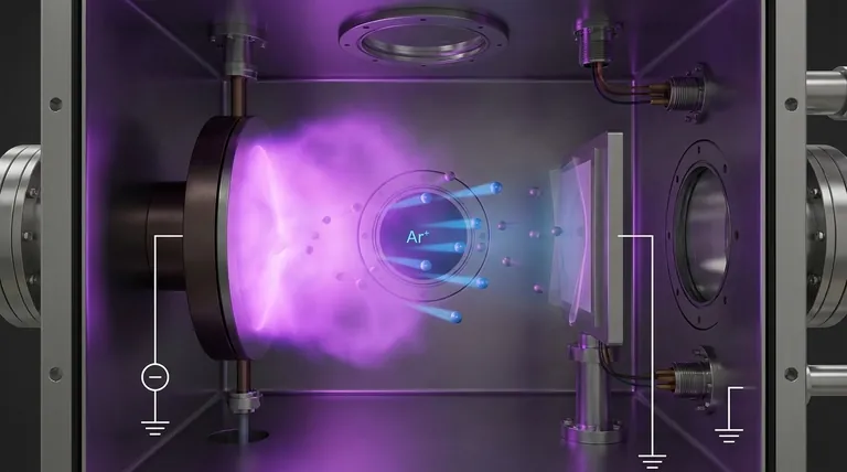
Step 3: Igniting the Plasma
When the high voltage is applied, the electric field between the cathode and anode energizes the chamber. This field strips electrons from the Argon atoms, creating a mixture of free electrons and positively charged Argon ions (Ar+). This ionized gas is known as a plasma.
Step 4: Ion Acceleration and Collision
The powerful negative charge of the cathode (the target) exerts an immense attraction on the newly formed, positively charged Ar+ ions.
These ions accelerate across the chamber and collide with the target surface with tremendous force.
Step 5: Ejection and Deposition
Each collision transfers kinetic energy from the Argon ion to the target. This energy is sufficient to physically knock atoms loose from the target's surface in a process analogous to a subatomic sandblasting.
These ejected target atoms travel through the vacuum until they land on the substrate, gradually building up a uniform thin film. This is the essence of physical vapor deposition (PVD).
The Critical Role of Magnetrons
Modern sputtering systems almost always use magnets behind the cathode, a technique known as magnetron sputtering.
Trapping Electrons to Enhance Plasma
The magnetic field is configured to trap electrons in a confined region directly in front of the target's surface.
These trapped electrons spiral around the magnetic field lines, dramatically increasing the distance they travel. This significantly raises the probability that they will collide with and ionize more neutral Argon atoms.
The Result: A Denser, More Efficient Plasma
This effect creates a much denser and more intense plasma precisely where it's needed most—right at the target. This leads to a much higher rate of ion bombardment and, consequently, a much faster and more efficient deposition process.
Common Pitfalls to Avoid
The relationship between the components and process parameters is a delicate balance. Misunderstanding it can lead to poor results.
Improper Gas Pressure
The working pressure of the process gas is critical. If the pressure is too high, sputtered atoms will collide with gas atoms and scatter before reaching the substrate, reducing the deposition rate. If it's too low, the plasma will be unstable or extinguish entirely.
Contamination from a Poor Vacuum
Starting the process before reaching a sufficiently high base vacuum is a common mistake. Any residual air or moisture will be incorporated into the growing film, leading to poor adhesion, altered electrical properties, and overall low quality.
Ignoring Target Erosion
The sputtering process inherently erodes the target material. Over time, this erosion can become uneven, especially in magnetron systems, forming a "racetrack" groove. This unevenness can alter the deposition uniformity on the substrate if not properly managed.
Applying This to Your Goal
Your specific objective determines which part of the process you need to control most carefully.
- If your primary focus is film purity: Your main concern should be the quality of the initial base vacuum and the purity of the Argon process gas.
- If your primary focus is deposition rate: The key levers are the electrical power applied to the cathode and the strength and design of the magnetron assembly.
- If your primary focus is film uniformity: The geometry—specifically the distance and angle between the cathode target and your substrate—is the most critical factor to optimize.
Understanding the distinct roles of the cathode and anode is the first step to mastering the control and precision offered by the sputtering process.
Summary Table:
| Component | Role in Sputtering | Key Characteristic |
|---|---|---|
| Cathode | Holds the sputtering target; negatively charged to attract ions | Source of coating material |
| Anode | Typically the grounded vacuum chamber; completes the circuit | Provides a stable reference for the electric field |
Ready to achieve precise thin film deposition in your lab? The cathode and anode setup is the foundation of a reliable sputtering process. KINTEK specializes in high-performance lab equipment and consumables, including sputtering targets and systems, to meet your specific research and production goals. Contact our experts today to discuss how our solutions can enhance your coating quality and efficiency.
Visual Guide
Related Products
- Graphite Vacuum Furnace Negative Material Graphitization Furnace
- Iridium Dioxide IrO2 for Water Electrolysis
- Rotating Platinum Disk Electrode for Electrochemical Applications
People Also Ask
- What is the application of graphite furnace? Essential for High-Temp Material Processing & Synthesis
- What are the advantages of graphite furnace? Achieve High-Temperature Precision and Purity
- What is the graphite furnace used for? Achieve Extreme Heat Up to 3000°C in a Controlled Environment
- What is the principle of graphite furnace? Achieve Extreme Temperatures with Direct Resistive Heating
- What is a graphite furnace? Unlock Extreme Temperatures and Purity for Advanced Materials