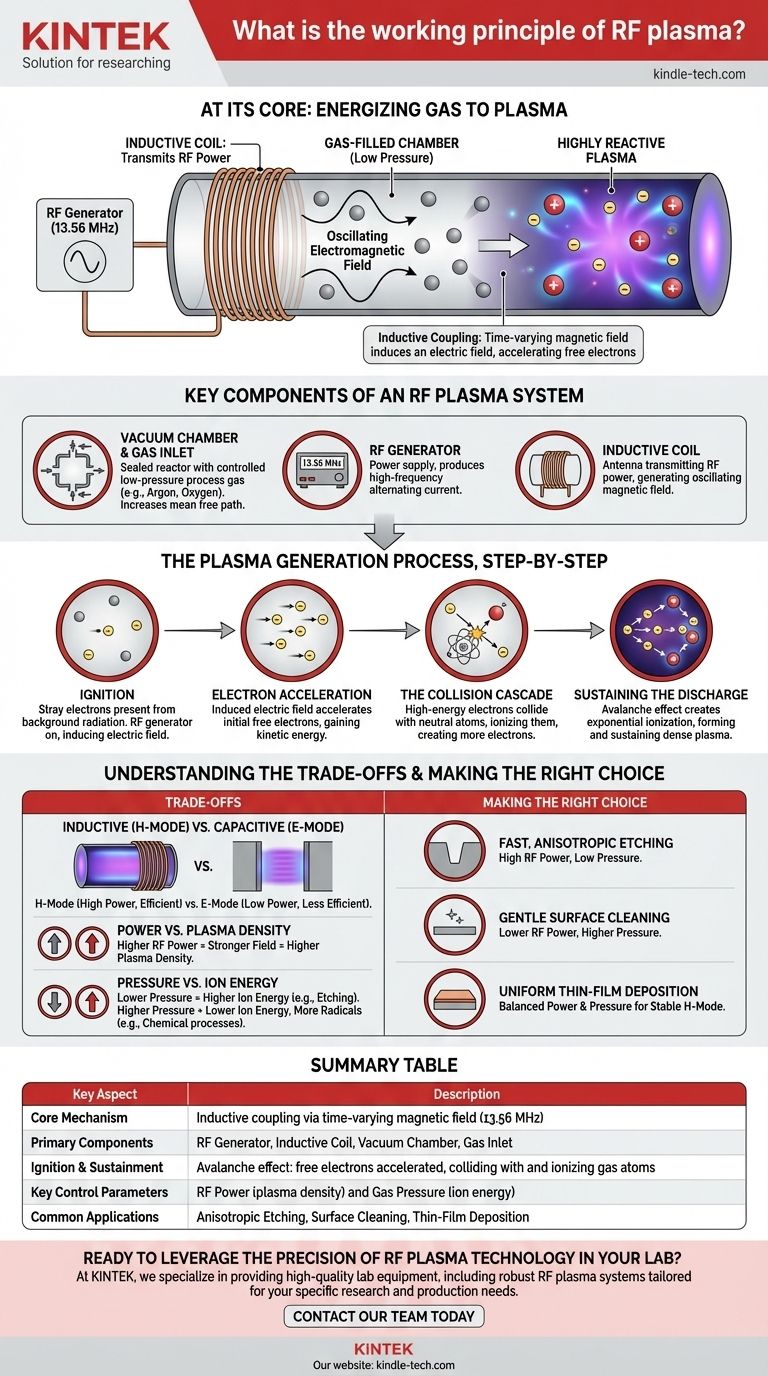
At its core, the working principle of RF plasma is the use of a high-frequency electromagnetic field to energize a gas to the point of ionization. A radio-frequency (RF) generator, typically operating at 13.56 MHz, sends an alternating current through an inductive coil wrapped around a gas-filled chamber. This creates a powerful, oscillating field inside the chamber that strips electrons from gas atoms, transforming the gas into a highly reactive plasma.
The central mechanism is inductive coupling. Instead of directly heating the gas, the system uses a time-varying magnetic field to induce an electric field within the chamber. This induced electric field accelerates free electrons, which then collide with and ionize neutral gas atoms in a self-sustaining cascade.
The Key Components of an RF Plasma System
To understand the principle, it's essential to recognize the function of each core component. These parts work in concert to create and sustain the plasma discharge.
The Vacuum Chamber and Gas Inlet
The entire process occurs within a sealed chamber, often called a cavity or reactor. A vacuum pump first removes most of the air before a specific process gas (like Argon, Oxygen, or Nitrogen) is introduced at a very low, controlled pressure.
This low pressure is critical. It increases the "mean free path"—the average distance an electron can travel before hitting a gas atom—allowing it to gain sufficient energy from the electric field for ionization.
The RF Generator
This is the power supply. It produces a high-frequency alternating current, standardized in most industrial applications at 13.56 MHz. This specific frequency is designated for Industrial, Scientific, and Medical (ISM) use, minimizing interference with communication systems.
The Inductive Coil
The coil is an antenna that transmits the RF power into the chamber. As the high-frequency current oscillates through the coil, it generates a correspondingly oscillating magnetic field that penetrates the chamber walls.
The Plasma Generation Process, Step-by-Step
The transformation from a neutral gas to a plasma happens in a rapid, multi-stage sequence.
Step 1: Ignition
Even in a neutral gas, a few stray free electrons are always present due to natural background radiation. When the RF generator is turned on, the oscillating magnetic field from the coil induces a circular electric field inside the chamber, perpendicular to the magnetic field.
Step 2: Electron Acceleration
This induced electric field is what does the work. It grabs onto those initial free electrons and accelerates them, causing them to oscillate rapidly and gain kinetic energy.
Step 3: The Collision Cascade
As these high-energy electrons zip through the low-pressure gas, they inevitably collide with neutral gas atoms. If an electron has absorbed enough energy from the field, the impact is strong enough to knock another electron off the atom.
This event creates two things: a positively charged ion and a second free electron. Now, there are two electrons available to be accelerated by the field.
Step 4: Sustaining the Discharge
This process repeats in an avalanche effect. The two electrons create four, the four create eight, and so on. This exponential cascade rapidly ionizes the gas, creating the dense, glowing mixture of ions, electrons, and neutral particles we recognize as plasma. The RF field continuously pumps energy into the electron population, which sustains the plasma.
Understanding the Trade-offs
The state of the plasma is not static; it is a delicate balance of competing factors. Understanding these trade-offs is key to controlling any plasma-based process.
Inductive vs. Capacitive Coupling
At very low power levels, the RF system may operate in a less efficient capacitive mode (E-mode). Here, the plasma is sustained by weaker electric fields that form between the coil and the chamber.
As power is increased past a certain threshold, the system abruptly transitions into the much more efficient inductive mode (H-mode). This mode produces a significantly denser and more uniform plasma, which is the desired state for most applications like etching and deposition.
Power vs. Plasma Density
Increasing the RF power directly increases the strength of the induced electric field. This accelerates electrons more forcefully, leading to more frequent ionizing collisions and a higher-density plasma (more ions and electrons per unit volume).
Pressure vs. Ion Energy
Gas pressure dictates the collision frequency. At lower pressures, electrons collide less often, allowing them to gain very high energy from the field before impact. This results in high-energy ion bombardment on a substrate, ideal for physical etching.
At higher pressures, electrons collide constantly and cannot gain as much energy between events. This creates a plasma with lower ion energy but more chemical radicals, which is better suited for purely chemical-driven processes.
Making the Right Choice for Your Goal
Controlling an RF plasma is about manipulating these fundamental principles to achieve a specific outcome on a material's surface.
- If your primary focus is fast, anisotropic etching: You need high RF power to ensure dense, inductive-mode plasma and low gas pressure to maximize the energy of the bombarding ions.
- If your primary focus is gentle surface cleaning or modification: You should use lower RF power and higher pressure to create a more chemical, less physically aggressive plasma that avoids damaging the substrate.
- If your primary focus is uniform thin-film deposition: You must carefully balance power and pressure to create a stable, inductive-mode plasma that provides a consistent flux of ions and radicals across the entire substrate.
Ultimately, mastering RF plasma is about precisely controlling the transfer of electromagnetic energy to a gas to achieve a desired material interaction.
Summary Table:
| Key Aspect | Description |
|---|---|
| Core Mechanism | Inductive coupling via a time-varying magnetic field (13.56 MHz) |
| Primary Components | RF Generator, Inductive Coil, Vacuum Chamber, Gas Inlet |
| Ignition & Sustainment | Avalanche effect: free electrons are accelerated, colliding with and ionizing gas atoms |
| Key Control Parameters | RF Power (controls plasma density) and Gas Pressure (controls ion energy) |
| Common Applications | Anisotropic Etching, Surface Cleaning, Thin-Film Deposition |
Ready to leverage the precision of RF plasma technology in your lab?
At KINTEK, we specialize in providing high-quality lab equipment, including robust RF plasma systems tailored for your specific research and production needs—whether it's for advanced etching, surface modification, or thin-film deposition. Our experts can help you select the right configuration to achieve superior process control and material results.
Contact our team today to discuss how our RF plasma solutions can enhance your laboratory's capabilities.
Visual Guide
Related Products
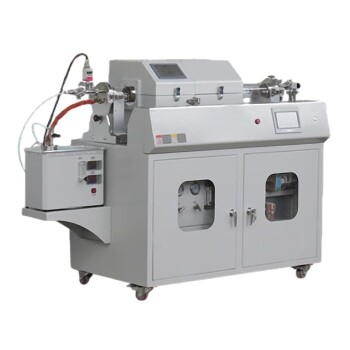
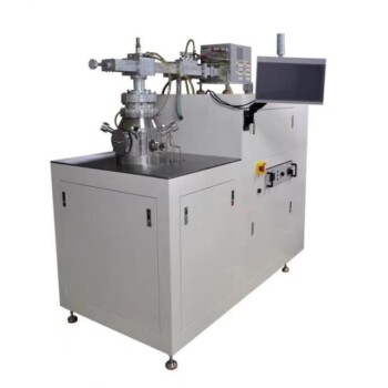
- Inclined Rotary Plasma Enhanced Chemical Vapor Deposition PECVD Equipment Tube Furnace Machine
- RF PECVD System Radio Frequency Plasma-Enhanced Chemical Vapor Deposition RF PECVD
- Chemical Vapor Deposition CVD Equipment System Chamber Slide PECVD Tube Furnace with Liquid Gasifier PECVD Machine
- Cylindrical Resonator MPCVD Machine System Reactor for Microwave Plasma Chemical Vapor Deposition and Lab Diamond Growth
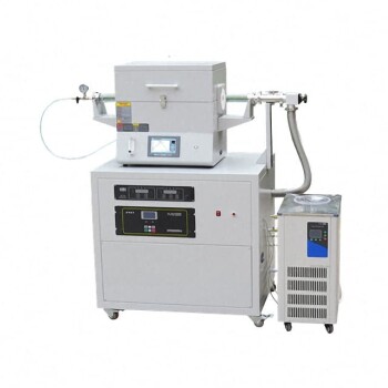
- Customer Made Versatile CVD Tube Furnace Chemical Vapor Deposition Chamber System Equipment
People Also Ask
- What is PECVD used for? Achieve Low-Temperature, High-Performance Thin Films
- What is the difference between PECVD and CVD? Unlock the Right Thin-Film Deposition Method
- What materials are deposited in PECVD? Discover the Versatile Thin-Film Materials for Your Application
- What is the difference between CVD and PECVD? Choose the Right Thin-Film Deposition Method
- What is PECVD silicon deposition? Achieve Low-Temperature, High-Quality Thin Films