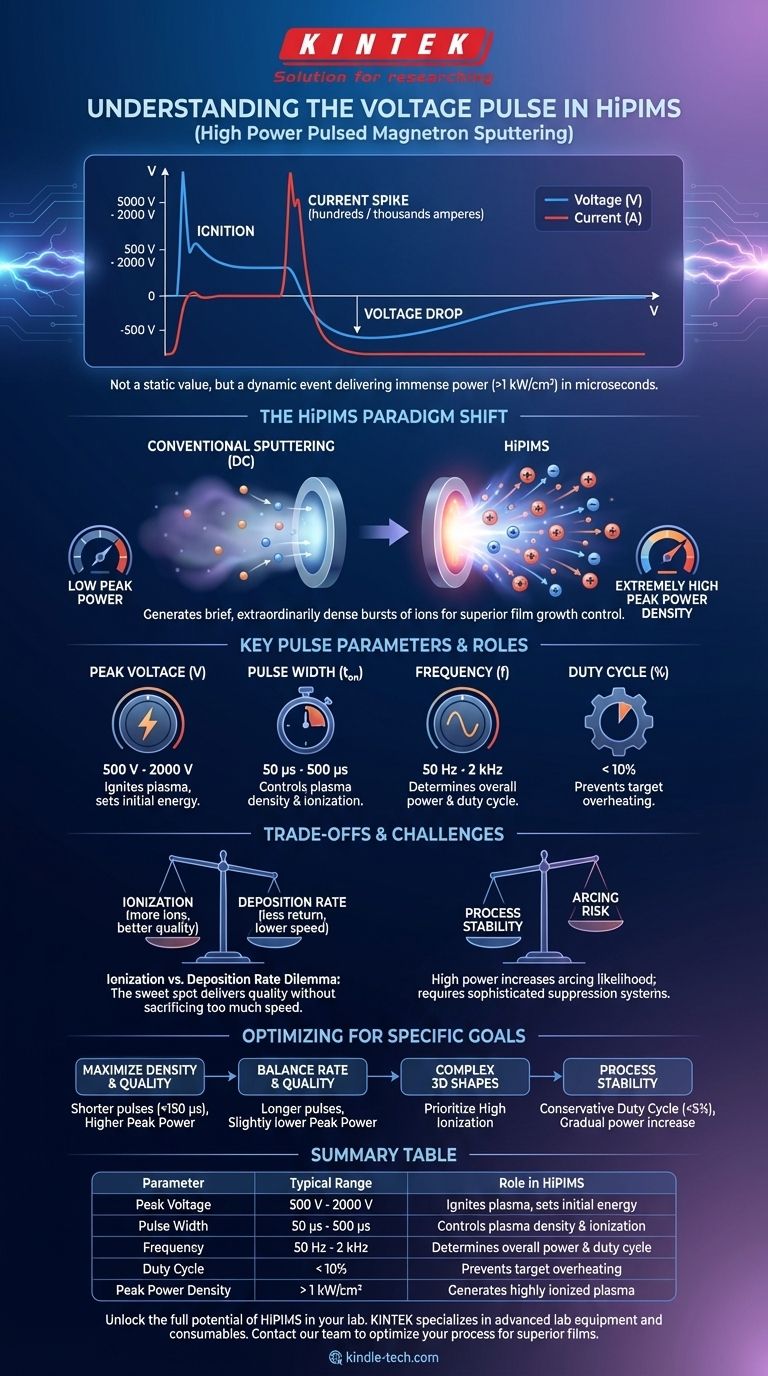
In High Power Pulsed Magnetron Sputtering (HiPIMS), the voltage pulse is not a simple, static value but a dynamic event characterized by high peak power and a low duty cycle. While initial voltages can range from 500 V to 2000 V, the key is the delivery of immense power (often >1 kW/cm²) in very short bursts (microseconds) to generate a highly ionized plasma.
The critical takeaway is that the HiPIMS voltage pulse is a tool to control plasma density and the ionization of sputtered material. Instead of focusing on a single voltage number, you must manage the relationship between voltage, current, pulse duration, and frequency to achieve your desired film properties.
From Voltage to Power Density: The HiPIMS Paradigm Shift
HiPIMS represents a fundamental departure from conventional sputtering methods like DC or RF. The goal is not merely to create a sustained plasma but to generate a brief, extraordinarily dense burst of ions.
Why HiPIMS Isn't Just "Pulsed DC"
The defining feature of HiPIMS is its extremely high peak power density on the target surface, often two or three orders of magnitude greater than DC magnetron sputtering.
This intense power burst is what creates a plasma with a very high fraction of ionized sputtered atoms. These ions can then be steered by electric or magnetic fields, enabling superior control over film growth.
The Anatomy of a HiPIMS Pulse
A typical HiPIMS pulse has a distinct electrical signature.
- Ignition: The pulse begins with a high voltage applied to the target, but the current is initially low as the plasma has not yet formed.
- Current Spike: As the gas breaks down and a dense plasma develops, the plasma impedance drops dramatically. This causes a massive spike in current, which can reach hundreds or even thousands of amperes.
- Voltage Drop: Due to the sharp increase in current and the limitations of the power supply, the voltage across the plasma simultaneously drops during the main phase of the pulse.
This dynamic V-I characteristic is the hallmark of a HiPIMS discharge.
Key Pulse Parameters and Their Roles
Controlling the process means controlling these four interconnected parameters:
- Peak Voltage (V): The initial voltage applied to ignite the plasma, typically 500 V to 2000 V.
- Pulse Width (t_on): The duration of the pulse, usually between 50 µs and 500 µs.
- Frequency (f): The number of pulses per second, commonly in the range of 50 Hz to 2 kHz.
- Duty Cycle: The percentage of time the power is on (
t_on * f). This is almost always kept below 10% to prevent overheating and melting the target.
How Pulse Characteristics Define Your Process
Tuning the voltage pulse gives you direct control over the plasma environment and, consequently, the properties of your deposited film.
The Effect on Ionization Fraction
Shorter, more intense pulses with higher peak power densities lead to a higher ionization fraction. A higher fraction of ionized deposition flux is the primary advantage of HiPIMS, enabling the growth of exceptionally dense and smooth films with excellent adhesion.
The Impact on Deposition Rate
The high ionization in HiPIMS can sometimes lead to a lower deposition rate compared to DC sputtering. This is because a portion of the newly created metal ions are attracted back to the negatively biased target, an effect known as ion return or self-sputtering.
Adjusting pulse length and power can help find a balance between high ionization and an acceptable deposition rate.
Controlling Film Properties
The energetic ion bombardment provided by HiPIMS allows for atomic-level manipulation of the growing film. By controlling the pulse, you can precisely engineer film properties like crystallinity, density, hardness, and internal stress. This is particularly useful for creating complex optical coatings or hard protective layers.
Understanding the Trade-offs and Challenges
While powerful, HiPIMS is not a universal solution and comes with inherent complexities that require careful management.
The Deposition Rate vs. Ionization Dilemma
This is the central trade-off in HiPIMS. The conditions that create the highest ionization (very high power, short pulses) also tend to maximize the ion return effect, thus reducing the deposition rate. Process optimization often involves finding the "sweet spot" that delivers sufficient ion flux for desired film quality without excessively sacrificing throughput.
Process Stability and Arcing
The extremely high power levels used in HiPIMS increase the likelihood of arcing on the target surface. Modern HiPIMS power supplies incorporate sophisticated arc detection and suppression systems that can extinguish an arc in microseconds, but it remains a key process consideration.
System Impedance Dynamics
The plasma impedance changes drastically within a single pulse. A power supply must be able to handle this dynamic load, delivering high voltage into an open circuit to start the pulse and then transitioning to deliver massive current into a low-impedance plasma.
Optimizing Your Pulse for Specific Goals
Your choice of pulse parameters should be driven by the primary goal of your deposition process.
- If your primary focus is maximizing film density and quality: Use shorter pulse widths (e.g., < 150 µs) and higher peak power to generate the highest possible ionization fraction for superior film densification.
- If your primary focus is balancing deposition rate and quality: Experiment with longer pulse widths or slightly lower peak power to reduce the ion return effect and increase the net deposition rate.
- If your primary focus is depositing on complex 3D shapes: Prioritize high ionization to ensure the deposition flux can be effectively guided to cover all surfaces conformally, even those not in the direct line of sight of the target.
- If your primary focus is process stability: Begin with a conservative duty cycle (<5%) and gradually increase power while monitoring the voltage and current waveforms to establish a stable operating window with minimal arcing.
By moving beyond a simple voltage setting, you begin to master the HiPIMS pulse, giving you unparalleled control over the fundamental properties of your thin film at the atomic level.
Summary Table:
| Parameter | Typical Range | Role in HiPIMS |
|---|---|---|
| Peak Voltage | 500 V - 2000 V | Ignites plasma, sets initial energy |
| Pulse Width | 50 µs - 500 µs | Controls plasma density & ionization |
| Frequency | 50 Hz - 2 kHz | Determines overall power & duty cycle |
| Duty Cycle | < 10% | Prevents target overheating |
| Peak Power Density | > 1 kW/cm² | Generates highly ionized plasma |
Unlock the full potential of HiPIMS in your lab. KINTEK specializes in advanced lab equipment and consumables for thin-film deposition. Our experts can help you select the right magnetron sputtering system and optimize your HiPIMS process to achieve superior film density, adhesion, and conformal coverage on complex substrates. Contact our team today to discuss your specific application needs and discover how our solutions can enhance your research and production outcomes.
Visual Guide
Related Products
- RF PECVD System Radio Frequency Plasma-Enhanced Chemical Vapor Deposition RF PECVD
- Spark Plasma Sintering Furnace SPS Furnace
- Microwave Plasma Chemical Vapor Deposition MPCVD Machine System Reactor for Lab and Diamond Growth
- 915MHz MPCVD Diamond Machine Microwave Plasma Chemical Vapor Deposition System Reactor
- Chemical Vapor Deposition CVD Equipment System Chamber Slide PECVD Tube Furnace with Liquid Gasifier PECVD Machine
People Also Ask
- What is plasma CVD? Unlock Low-Temperature Thin Film Deposition for Sensitive Materials
- What is plasma enhanced chemical vapour deposition PECVD used for? Enable Low-Temp Thin Films for Electronics & Solar
- How does Radio Frequency Enhanced Plasma Chemical Vapour Deposition (RF-PECVD) work? Learn the Core Principles
- How does plasma enhance CVD? Unlock Low-Temperature, High-Quality Film Deposition
- What is the role of RF-PECVD in VFG preparation? Mastering Vertical Growth and Surface Functionality