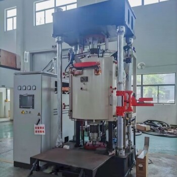
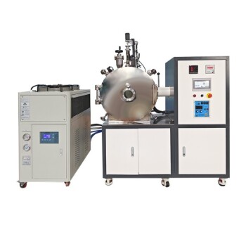
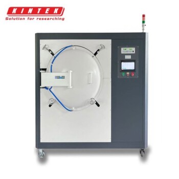
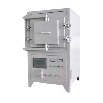
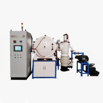
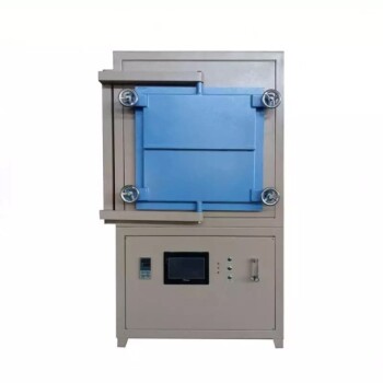
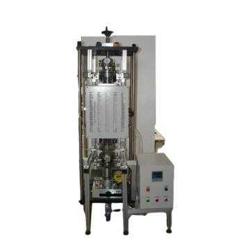
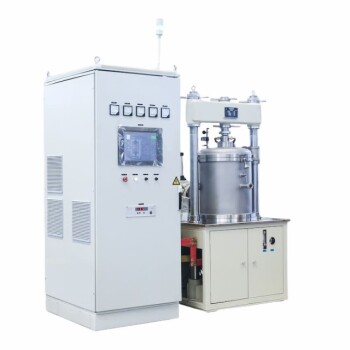
Vacuum Atmosphere Furnaces and Their Applications
Common Atmospheres Used
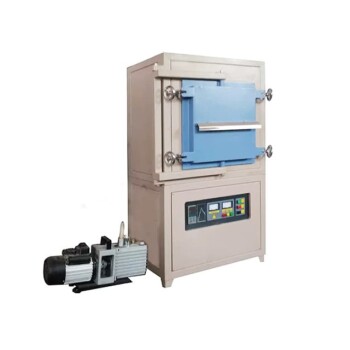
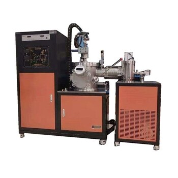
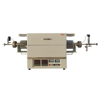
Vacuum atmosphere furnaces operate within a variety of controlled environments, each tailored to specific processing needs. These atmospheres include:
- Vacuum: Ideal for processes requiring minimal gas interference, such as high-temperature sintering and metal degassing.
- Hydrogen: Used for reducing atmospheres, essential in processes like carburizing and annealing, where hydrogen acts as a reducing agent.
- Oxygen: Often employed in oxidation processes, crucial for applications involving the formation of oxide layers.
- Nitrogen: Commonly used as a protective atmosphere to prevent oxidation and decarburization during heat treatment.
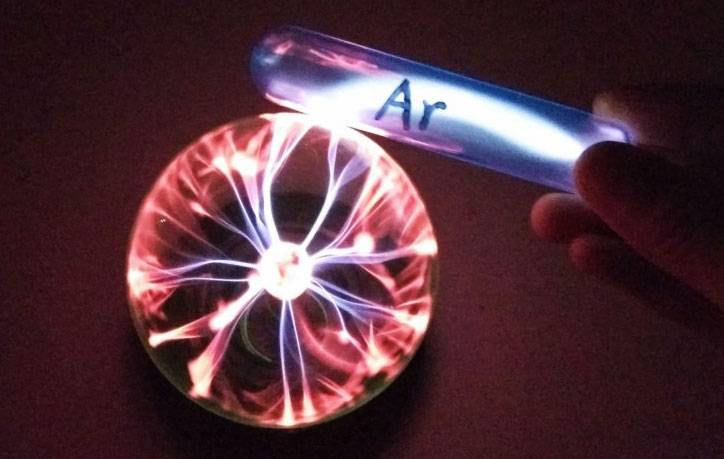
- Inert Gases (e.g., Argon): Provide a non-reactive environment, suitable for processes where contamination must be avoided, such as in the production of high-purity metals.
Each of these atmospheres serves distinct purposes, ensuring that the furnace can accommodate a wide range of industrial applications, from ceramics and metallurgy to electronics and chemical processing.
Widespread Usage
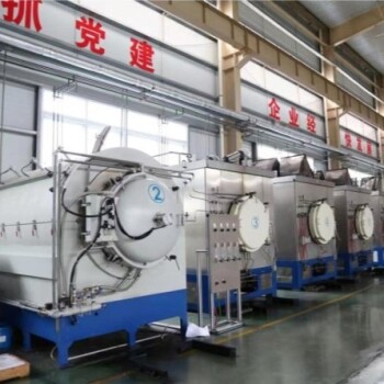
Vacuum atmosphere furnaces have become indispensable tools across a broad spectrum of industries. Their applications span from ceramics and metallurgy to electronics and glass manufacturing. In the chemical industry, these furnaces are often employed for precise material processing, ensuring optimal results in complex reactions. The machinery sector benefits from their use in high-temperature experiments and material testing, while refractory materials and special materials industries rely on them for processes like powder roasting and ceramic sintering. Additionally, the building materials sector utilizes these furnaces for various thermal treatments, highlighting their versatility and critical role in modern manufacturing and research.
Gas Tightness and Leakage Standards
Performance Characteristics
The gas tightness of the vacuum system in a vacuum atmosphere furnace is a critical parameter that defines its ability to prevent gas leakage. This characteristic is influenced by two primary factors: the leakage through physical holes or gaps in the system, and the permeability of the materials used in its construction. The effectiveness of the vacuum system in maintaining a sealed environment is typically quantified by its leakage rate.
To better understand the significance of gas tightness, consider the following aspects:
-
Leakage Holes and Gaps: Any physical imperfections, such as cracks or gaps, can serve as pathways for gas to escape. The smaller and fewer these pathways, the better the gas tightness.
-
Material Permeability: Even without visible holes, materials can allow gas molecules to pass through via diffusion. High-quality materials with low permeability are essential for maintaining a vacuum.
-
Leakage Rate: This is the measure of how much gas escapes the system over a given period. A lower leakage rate indicates superior gas tightness.
| Aspect | Description |
|---|---|
| Leakage Holes | Physical imperfections that allow gas to escape. |
| Material Permeability | The ability of materials to resist gas diffusion. |
| Leakage Rate | The amount of gas escaping per unit time, lower is better. |
In summary, the gas tightness of a vacuum system is a multifaceted attribute that hinges on the integrity of its physical structure and the properties of its materials. The leakage rate serves as a practical metric to evaluate and compare the performance of different vacuum systems.
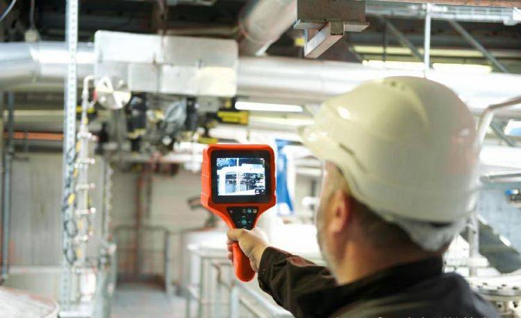
Leakage Rate Definition
The leakage rate, as defined in the standard, is a critical parameter that quantifies the amount of gas passing through a leakage hole under specific conditions. Specifically, the standard stipulates that the leakage rate is measured when the inlet pressure of the leakage hole is set at 1 * 0.1 * 10^5 Pa, while the outlet pressure remains below 1.33 * 10^3 Pa. These measurements are taken under standard conditions, which include a temperature range of 23°C ± 7°C and a dew point temperature of less than -25°C for the air used in the test.
To put it simply, the leakage rate is the volume of gas that escapes through a leak in a unit of time. This rate is crucial for assessing the integrity and performance of vacuum systems, particularly in applications like vacuum atmosphere furnaces. A lower leakage rate generally indicates a better-sealed system, which is essential for maintaining the desired vacuum conditions and ensuring the accuracy and reliability of the processes being conducted within the furnace.
| Parameter | Value |
|---|---|
| Inlet Pressure | 1 * 0.1 * 10^5 Pa |
| Outlet Pressure | < 1.33 * 10^3 Pa |
| Temperature | 23°C ± 7°C |
| Dew Point Temperature | < -25°C |
Understanding the leakage rate is fundamental for any vacuum system operator or engineer, as it directly impacts the overall efficiency and effectiveness of the system. By adhering to these standardized conditions and measuring the leakage rate accurately, one can ensure that the vacuum atmosphere furnace operates at its optimal level, minimizing any potential issues related to gas leakage.
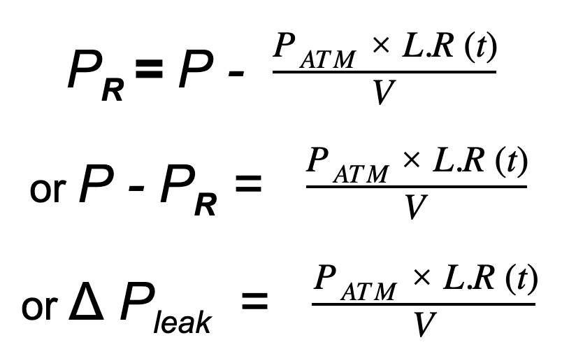
Purpose and Principles of Vacuum Leak Detection
Purpose of Leak Detection
The primary objective of vacuum leak detection extends beyond merely identifying whether a system is experiencing gas leakage and quantifying the magnitude of the leakage rate. It is also crucial to pinpoint the exact location of the leak, whether it be a physical hole or a more subtle cause, such as material permeability. This precise identification is essential for implementing targeted corrective actions to repair the system.
To illustrate the importance of locating leaks, consider the following scenarios:
| Scenario | Potential Impact | Action Required |
|---|---|---|
| Physical Hole | Rapid gas loss, system failure | Seal the hole, replace damaged parts |
| Material Permeability | Slow, continuous gas loss, compromised performance | Replace permeable materials, apply barrier coatings |
By accurately identifying the source of the leak, technicians can ensure that the necessary repairs are made efficiently and effectively, thereby maintaining the integrity and performance of the vacuum system.
Basic Principle of Leak Detection
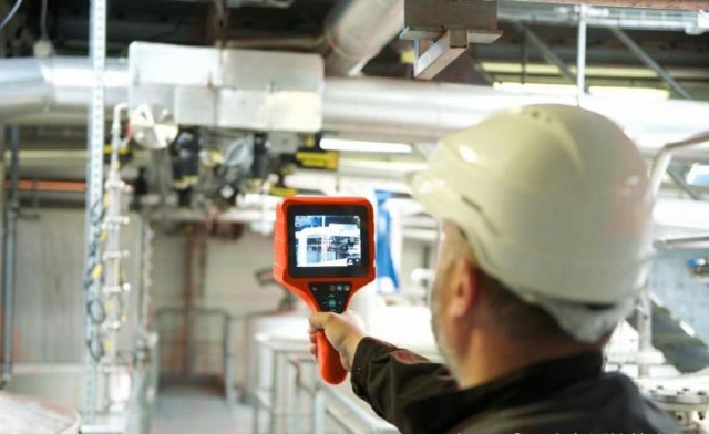
The fundamental principle of leak detection in vacuum systems involves leveraging the pressure differential between the interior and exterior of the system to induce gas flow. This flow is then monitored using specific technical methods to pinpoint the location of any leakage holes. One common approach is the positive pressure leakage detection method. In this method, the vacuum system is filled with gas at a pressure higher than atmospheric pressure. This creates a pressure gradient that forces gas to flow from the inside of the system to the outside, facilitating leakage detection. A leak detector probe is then used to detect the escaping gas from the outside, enabling the identification of both the location of the leakage holes and the rate at which gas is leaking.
Another method is the negative pressure leak testing, also known as the vacuum leak testing method. Here, the vacuum system is pumped down to a pressure lower than atmospheric pressure. Leakage gas is then sprayed onto the system from the outside using a nozzle. This causes the gas to flow from the outside to the inside of the system. By observing the changes in the readings of the leak detector, one can determine both the location of the leakage holes and the leakage rate.
Both methods are crucial for ensuring the integrity of vacuum systems, particularly in applications such as vacuum atmosphere furnaces, where maintaining a controlled environment is essential for the process outcomes.
Negative Pressure Leak Testing
Negative pressure leak testing, also known as vacuum leak testing, is a method employed to identify and quantify leaks in a vacuum system. This process involves several key steps:
-
Creating a Vacuum: The vacuum system is first pumped down to a vacuum state. This step ensures that any subsequent gas flow can be easily detected and measured.
-
Introducing Leakage Gas: A specialized nozzle is used to spray a detectable gas (commonly helium in industrial applications) onto the exterior surfaces of the system. This gas is chosen for its ability to easily penetrate small leaks and its detectability using modern leak detection equipment.
-
Observing Gas Flow: As the leakage gas encounters any defects in the system, it flows from the outside to the inside due to the pressure differential. This inward flow of gas is then detected by a leak tester.
-
Analyzing Readings: The leak tester monitors and records changes in its readings, which correspond to the presence and magnitude of gas flow through the leaks. These readings help in pinpointing the exact locations of the leaks and determining the leakage rate.
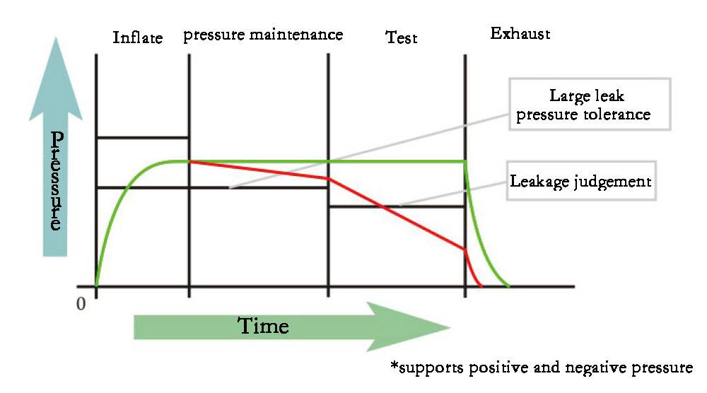
This method is particularly effective because it allows for the detection of even the smallest leaks, ensuring that the vacuum system maintains its integrity and performance. By understanding the location and rate of leaks, corrective actions can be taken to repair the system, thereby preventing potential issues that could arise from prolonged exposure to leaks.
| Step | Description |
|---|---|
| 1 | Creating a Vacuum: System is pumped down to a vacuum state. |
| 2 | Introducing Leakage Gas: Detectable gas is sprayed onto the exterior. |
| 3 | Observing Gas Flow: Gas flows inward through leaks. |
| 4 | Analyzing Readings: Leak tester records and interprets data to locate and quantify leaks. |
Related Products
- Vacuum Heat Treat Sintering Brazing Furnace
- Controlled Nitrogen Inert Hydrogen Atmosphere Furnace
- Molybdenum Vacuum Heat Treat Furnace
- Vacuum Heat Treat and Pressure Sintering Furnace for High Temperature Applications
- Lab-Scale Vacuum Induction Melting Furnace
Related Articles
- Why Your High-Performance Parts Fail in the Furnace—And How to Fix It for Good
- Mastering Vacuum Furnace Brazing: Techniques, Applications, and Advantages
- The Engineering of Nothingness: Why Vacuum Furnaces Define Material Integrity
- Materials Science with the Lab Vacuum Furnace
- Vacuum Induction Melting Furnace: Principle, Advantages, and Applications
