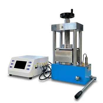
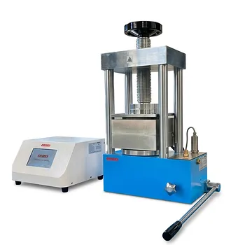
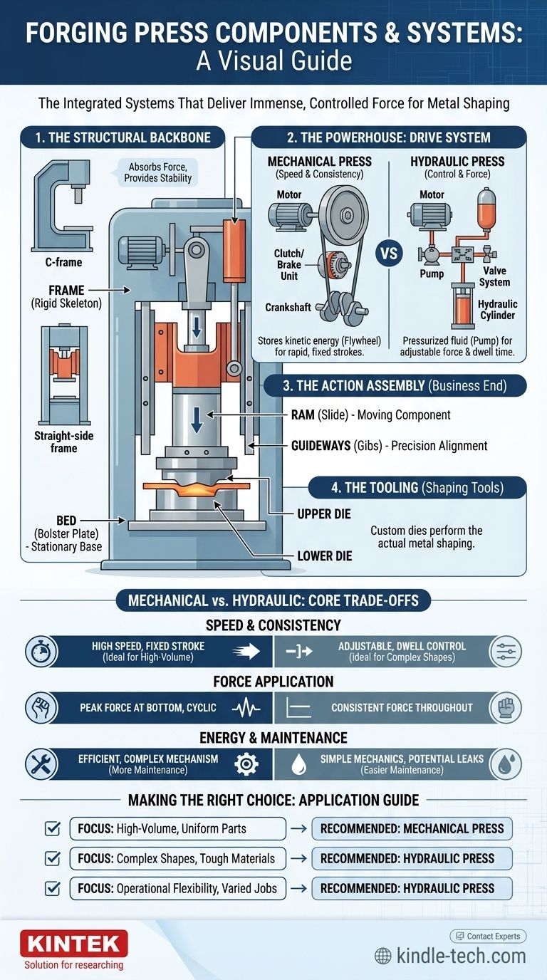
At its core, a forging press is a machine that shapes metal through compressive force. Its primary components can be grouped into four key systems: the structural frame that provides rigidity, the drive system that generates power, the slide assembly that transmits this power, and the tooling that performs the actual shaping. While designs vary, these fundamental elements work in concert to deliver immense, controlled force.
A forging press is not just a collection of parts, but an integrated system designed to deliver and withstand enormous forces. Understanding how the structure, power source, and tooling interact is essential to grasping its function and capabilities.
The Anatomy of a Forging Press
A forging press is best understood by breaking it down into its core functional systems. Each system contains several critical components that are essential for the forging process.
The Structural Backbone: Frame and Bed
The frame is the skeleton of the press, responsible for absorbing the immense forces generated during operation.
- Frame: This is the main structure of the press. The most common designs are the C-frame (offering open access on three sides) and the straight-side frame (providing superior rigidity and precision for heavy-duty forging).
- Bed (or Bolster Plate): The bed is the stationary base of the press where the lower forging die is mounted. It must be perfectly flat and robust enough to support the full force of the operation without deflection.
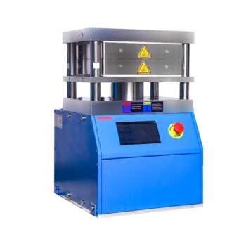
The Powerhouse: Drive and Transmission System
This system creates the energy needed for forging. The components differ significantly between the two main types of presses: mechanical and hydraulic.
- Electric Motor: The prime mover for virtually all modern presses, providing the initial rotational energy.
- Flywheel (Mechanical Press): In a mechanical press, the motor spins a massive flywheel, which stores kinetic energy. This stored energy is then released in a burst during the forging stroke.
- Clutch and Brake (Mechanical Press): The clutch engages the flywheel to the transmission, initiating the press stroke. The brake disengages it, stopping the ram precisely at the top of its stroke.
- Crankshaft or Eccentric Drive (Mechanical Press): This mechanism converts the rotational motion from the flywheel and clutch into the reciprocating (up-and-down) motion of the ram.
- Hydraulic System (Hydraulic Press): In a hydraulic press, the motor drives a pump that pressurizes hydraulic fluid. This fluid is stored in an accumulator and controlled by a series of valves to actuate the main cylinder.
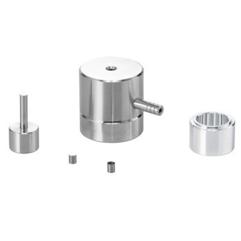
The Action Assembly: Ram and Tooling
This is the "business end" of the press, where the force is applied to the workpiece.
- Ram (or Slide): The ram is the moving component of the press that travels up and down. It holds the upper forging die and must be guided with extreme precision by guideways (gibs) to ensure alignment.
- Pitman Arm (Mechanical Press): This arm connects the crankshaft to the ram, driving its vertical motion.
- Hydraulic Cylinder (Hydraulic Press): A large piston and cylinder assembly drives the ram. The force applied is directly proportional to the hydraulic pressure and the piston's surface area.
- Dies (Upper and Lower): These are the custom tools that are mounted to the ram and bed. Their cavities contain the negative impression of the final forged part. They are built from highly durable tool steel to withstand repeated impact and high temperatures.
Mechanical vs. Hydraulic: Understanding the Core Trade-offs
The choice between a mechanical and hydraulic press is driven by the components of their drive systems, which create distinct operational advantages and disadvantages.
Speed and Stroke Consistency
A mechanical press is defined by its fixed stroke length and high operational speed. The flywheel system is designed for rapid, repeatable cycles, making it ideal for high-volume production of relatively simple parts.
Force and Dwell Time Control
A hydraulic press offers superior control. The force can be applied consistently throughout the entire stroke, and the stroke length, speed, and dwell time (the time the die remains closed under pressure) are all fully adjustable. This makes it suitable for complex shapes, deep-drawing operations, and materials that are difficult to form.
Energy and Maintenance
Mechanical presses are generally more energy-efficient for high-speed, continuous work because they leverage the stored energy of the flywheel. However, their complexity (clutch, brake, crankshaft) can lead to higher maintenance demands.
Hydraulic presses can consume more energy as the pump often runs continuously, but their simpler mechanical design (fewer moving parts) can ease maintenance. Leaks in the hydraulic system are a primary concern.
Making the Right Choice for Your Application
Understanding the components and their interplay allows you to select the right tool for the job.
- If your primary focus is high-volume production of uniform parts: A mechanical press is superior due to its speed and consistent stroke cycle.
- If your primary focus is forming complex shapes or difficult materials: A hydraulic press offers the necessary control over force, speed, and dwell time.
- If your primary focus is operational flexibility for varied jobs: A hydraulic press provides the adjustability needed to handle a wider range of part geometries and material types.
Ultimately, the components of a forging press are a direct reflection of its intended function and its operational philosophy.
Summary Table:
| Component System | Key Parts | Primary Function |
|---|---|---|
| Structural Frame | Frame (C-frame or Straight-side), Bed/Bolster Plate | Provides rigidity and absorbs immense forging forces. |
| Drive System | Electric Motor, Flywheel, Clutch/Brake, Crankshaft (Mechanical) or Hydraulic Pump, Cylinder, Valves (Hydraulic) | Generates and transmits the power needed for the forging stroke. |
| Ram Assembly | Ram/Slide, Guideways (Gibs), Pitman Arm (Mechanical) or Hydraulic Cylinder (Hydraulic) | Transmits force from the drive system to the tooling with precision. |
| Tooling | Upper and Lower Dies | Custom tools that perform the actual shaping of the metal workpiece. |
Ready to Select the Right Forging Press for Your Lab or Production Line?
Understanding the components is the first step. Choosing the right press is critical for your efficiency, precision, and bottom line. Whether you need the high-speed consistency of a mechanical press or the flexible control of a hydraulic press, KINTEK has the expertise and equipment to meet your specific metal shaping challenges.
Let KINTEK, your trusted partner in lab equipment and consumables, help you:
- Optimize your forging process with the right press technology.
- Increase production throughput with reliable, high-performance machinery.
- Achieve superior part quality through precise force and stroke control.
Don't leave your production to chance. Contact our experts today for a personalized consultation and discover the KINTEK difference in durability and performance.
Visual Guide
Related Products
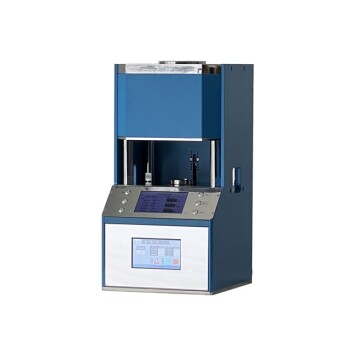
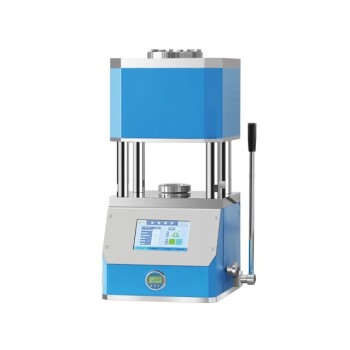
- Automatic High Temperature Heated Hydraulic Press Machine with Heated Plates for Lab
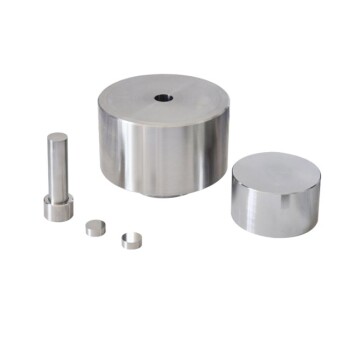
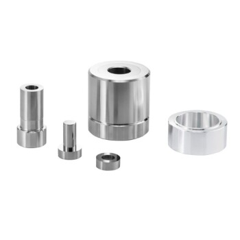
- Anti-Cracking Press Mold for Lab Use
- Special Shape Press Mold for Lab
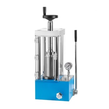
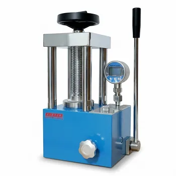
- Manual Cold Isostatic Pressing Machine CIP Pellet Press
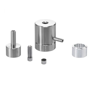
- Ring Press Mold for Lab Applications
People Also Ask
- Why is a heated hydraulic press used for warm pressing NASICON green tapes? Optimize Your Solid Electrolyte Density
- Why is the heating function of a laboratory hydraulic press essential for MEA assembly in DEFC? Optimize Cell Bonding
- What role does a heated hydraulic press play in Cold Sintering (CSP)? Enhancing LATP-Halide Densification
- What technical conditions does a heated hydraulic press provide for PEO batteries? Optimize Solid-State Interfaces
- What is a heated hydraulic press used for? Essential Tool for Curing, Molding, and Laminating