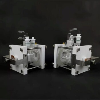
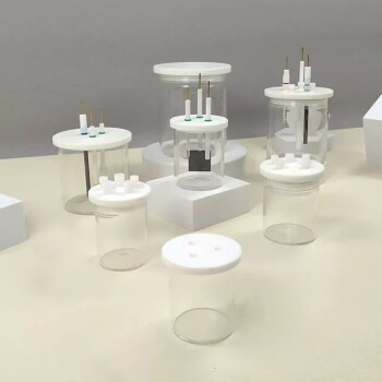
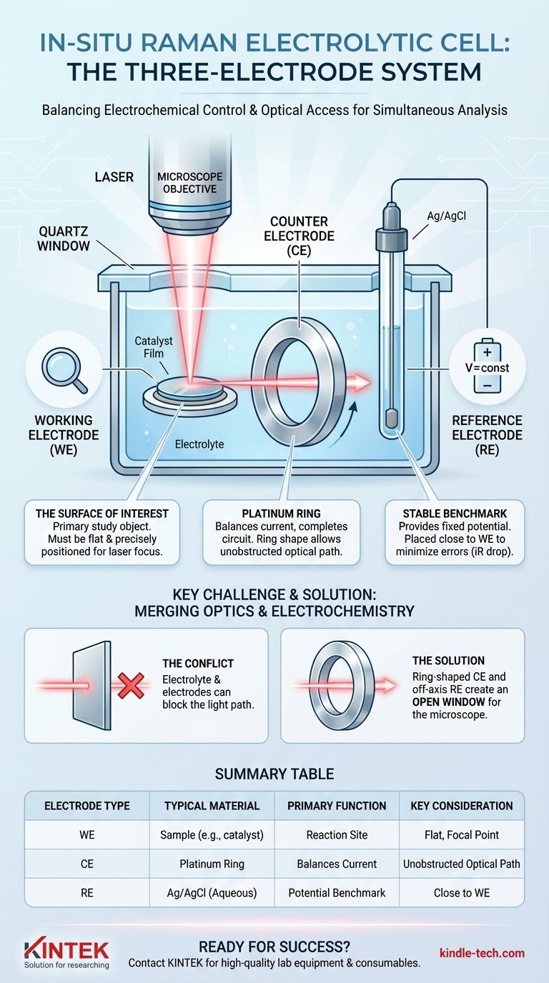
The standard configuration for an in-situ Raman electrolytic cell uses a three-electrode system designed to balance electrochemical control with optical access. This typically consists of the sample being studied as the working electrode, an inert platinum wire as the counter electrode, and a stable Ag/AgCl electrode as the reference electrode. The specific geometry of these components is critical for allowing a microscope objective to focus on the working electrode's surface during the experiment.
The core challenge of in-situ Raman electrochemistry is not just controlling a reaction, but doing so while maintaining a clear, unobstructed optical path for the laser. The design and arrangement of the three electrodes are engineered specifically to solve this problem, enabling simultaneous electrochemical measurement and spectroscopic analysis.
The Role of Each Electrode in the System
A three-electrode setup is the foundation of modern electrochemistry. It allows for the precise control and measurement of the working electrode's potential, independent of the bulk solution resistance or reactions occurring at the counter electrode.
The Working Electrode (WE): The Surface of Interest
The working electrode is the primary object of your study. This is the surface where the electrochemical reaction you want to observe with the Raman spectrometer is taking place.
While a platinum clip can be used to hold a sample, the WE itself is the material you are investigating. This could be a thin film of a catalyst deposited on a substrate (like gold or glassy carbon), a single crystal, or a powder pressed into a solid disk. Its surface must be positioned precisely at the focal point of the Raman microscope.
The Counter Electrode (CE): Balancing the Current
The counter electrode, also called the auxiliary electrode, completes the electrical circuit. It passes all the current needed to drive the reaction at the working electrode, ensuring no net current flows through the reference electrode.
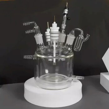
In in-situ cells, the CE is often a platinum wire ring. This clever design allows the microscope objective to look directly through the center of the ring to focus on the working electrode below it. Platinum is chosen because it is chemically inert and has high catalytic activity for common electrolyte reactions (like water splitting), preventing it from becoming the limiting factor in the experiment.
The Reference Electrode (RE): The Stable Benchmark
The reference electrode provides a stable, constant potential against which the potential of the working electrode is measured and controlled. It acts as a fixed zero-point for your electrochemical measurements.
A Silver/Silver Chloride (Ag/AgCl) electrode is a common and reliable choice for aqueous systems. The tip of the RE is placed as close as possible to the working electrode to minimize measurement errors caused by voltage drop through the electrolyte (known as iR drop).
Why This Configuration is Essential for In-Situ Raman
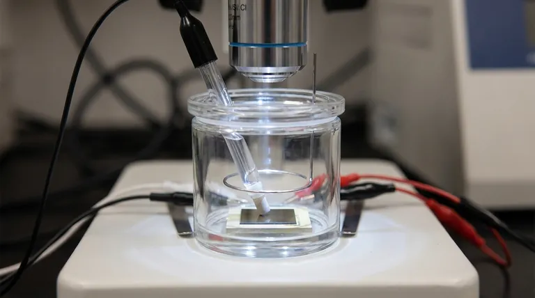
The goal is to get a clean Raman signal from the WE surface while it is actively participating in an electrochemical reaction. This presents a significant design challenge.
The Challenge: Merging Optics and Electrochemistry
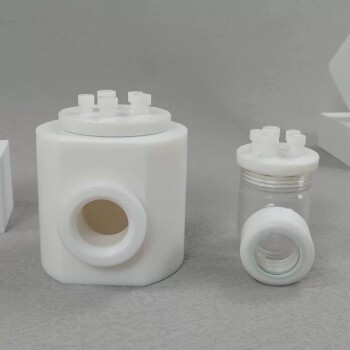
You must submerge the WE in an electrolyte and control its potential, but you also need to focus a laser onto its surface and collect the scattered light. The electrolyte, the other electrodes, and the cell body itself can all block the light path or degrade the signal.
The Solution: An Unobstructed Optical Path
The typical cell design solves this by creating a clear line of sight from the top down. The ring-shaped counter electrode and the off-axis placement of the reference electrode work together to create an open window for the microscope objective.
Furthermore, the distance between the cell's quartz window and the WE surface is minimized. This ensures the laser travels through the thinnest possible layer of electrolyte, reducing signal absorption and scattering by the solution.
Understanding the Trade-offs
While the standard configuration is effective, it is not without compromises. Achieving reliable results requires understanding these inherent trade-offs.
Electrode Placement vs. Measurement Accuracy
Placing the reference electrode tip very close to the working electrode is ideal for minimizing iR drop and ensuring accurate potential control. However, placing it too close can interfere with the electrolyte flow or, in some geometries, partially obstruct the optical path.
Material Selection is Not Universal
Platinum is an excellent, inert material for a counter electrode in many situations. However, if platinum ions could potentially dissolve and re-deposit on your working electrode (poisoning it) or interfere with your reaction, you may need to choose an alternative like a graphite rod or isolate the CE in a separate compartment.
Working Electrode Form Factor
The "platinum clip" mentioned in standard descriptions is simply a holder. The actual working electrode must be prepared in a way that is both electrochemically active and flat enough for Raman microscopy. This can be challenging for powders or non-conductive materials, which may require mixing with a binder and pressing into a pellet.
Making the Right Choice for Your Experiment
Your experimental goal should dictate your final setup. Use the standard configuration as a starting point and adapt it as needed.
- If your primary focus is studying catalytic films: Use a flat, polished substrate (like gold, platinum, or glassy carbon) as your working electrode to ensure a uniform surface for analysis.
- If your primary focus is maximizing signal quality: Ensure the electrolyte layer above your working electrode is as thin as possible (typically <1-2 mm) without allowing the surface to dry out.
- If your primary focus is potential accuracy: Position the tip of your reference electrode as close as you can to the working electrode without physically blocking the laser path or shadowing the surface.
By understanding the distinct role of each electrode and the optical requirements of the measurement, you can configure your in-situ cell to capture high-quality, meaningful data.
Summary Table:
| Electrode Type | Typical Material | Primary Function | Key Design Consideration |
|---|---|---|---|
| Working Electrode (WE) | Sample material (e.g., catalyst film) | Surface where reaction of interest occurs | Must be flat and positioned at the microscope's focal point |
| Counter Electrode (CE) | Platinum wire/ring | Completes the circuit, balances current | Often ring-shaped to allow unobstructed optical access |
| Reference Electrode (RE) | Ag/AgCl (aqueous) | Provides a stable potential benchmark | Placed close to WE to minimize measurement error (iR drop) |
Ready to configure your in-situ Raman experiment for success? The right lab equipment is crucial for achieving clear optical paths and precise electrochemical control. KINTEK specializes in high-quality lab equipment and consumables, including electrolytic cells and electrodes, to serve your laboratory's advanced research needs.
Contact our experts today to discuss how we can support your specific application and help you capture high-quality, meaningful data.
Visual Guide
Related Products
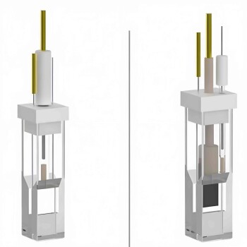
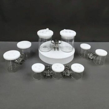
- Thin-Layer Spectral Electrolysis Electrochemical Cell
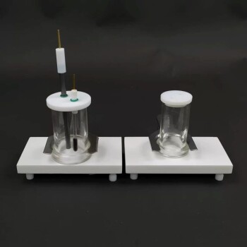
- Electrolytic Electrochemical Cell for Coating Evaluation
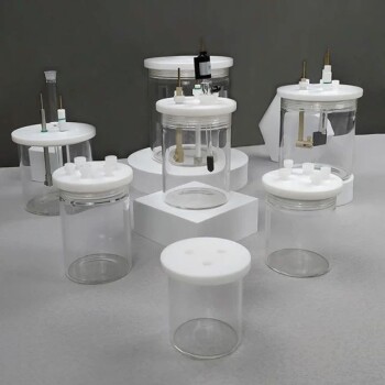
- Electrolytic Electrochemical Cell with Five-Port
- Electrolytic Electrochemical Cell Gas Diffusion Liquid Flow Reaction Cell
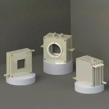
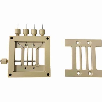
- Flat Corrosion Electrolytic Electrochemical Cell
People Also Ask
- For what types of systems, temperature ranges, and sealing configurations is the thin-layer spectroelectrochemical cell designed? Ideal for Aqueous and Non-Aqueous Analysis
- What are the physical dimensions of the thin-layer spectroelectrochemical cell body and its slit? Key Specs for Your Lab
- What preparation steps are required before initiating an experiment with the thin-layer spectroelectrochemical cell?
- What are the construction materials and design features of the thin-layer spectroelectrochemical cell body? Explored
- What are the general operating procedures for a thin-layer spectroelectrochemical cell during an experiment? Master Synchronized Data Collection